6-12 VersaMax® Modules, Power Supplies, and Carriers User's Manual – March 2003 GFK-1504K
6
IC200ERM002
Expansion Receiver Module, Non-isolated
Connectors
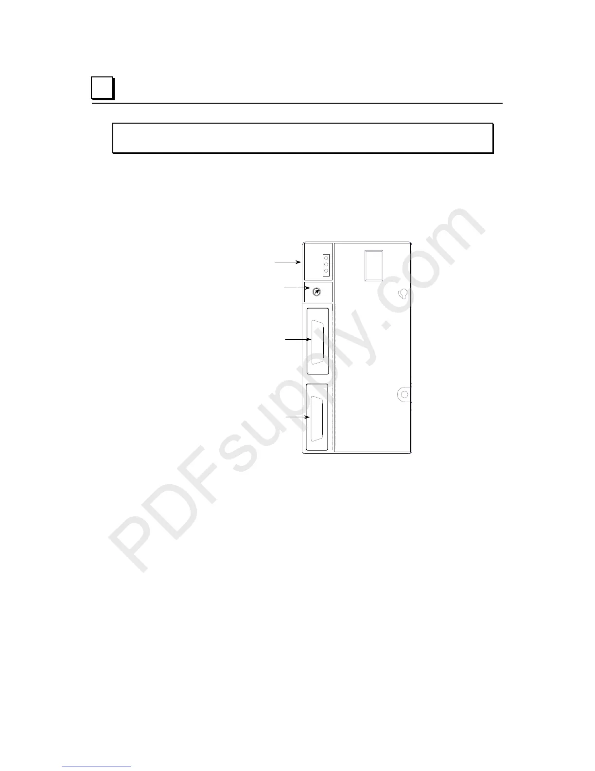
The Expansion Receiver has two 26-pin female D-shell expansion ports. The upper
port receives the cable from an Expansion Transmitter or upstream Expansion
Receiver Module. The lower port is used to connect the expansion cable to the next
expansion rack or to attach the terminator plug at the last rack.
Expansion Rack
Selection Switch
LEDs
Expansion Port for
Incomin
cable
Expansion Port for
Continuing Cable or
Termination Plug
5
7
6
4
1
3
2
ERM002
PWR
EXP RX
SCAN
Ex nV II T4 Demko No
.
.
.
.
.
.
.
.
.
.
.
.
.
.
.
.
.
.
.
.
.
.
.
.
.
.
.
.
.
.
.
.
.
.
.
.
.
.
.
.
.
.
.
.
.
.
.
.
.
.
.
.
EXP 1
EXP 2
0
LED Indicators
Three LEDs show the status of module power, the expansion port, and the I/O
modules.
The PWR LED is On when the module is receiving 5VDC power from the attached
power supply. It is Off when there is no power supply attached or when the power
supply itself is not receiving power.
The SCAN LED lights green when the CPU/NIU is actively scanning I/O in
expansion racks. It lights amber when the CPU/NIU is not actively scanning I/O in
expansion racks.
The EXP RX LED indicates the status of the expansion bus. This LED is either
blinking or On when the Expansion Receiver is communicating with the Expansion
Transmitter or with other ERMs. It is Off when not communicating.
Expansion Rack Selection Switch
The Rack Selection Switch is used to specify which expansion rack the ERM is in.