8-16 VersaMax® Modules, Power Supplies, and Carriers User's Manual – March 2003 GFK-1504K
8
IC200MDL730
Output Module, 24VDC Positive Logic 2.0 Amps, w/ESCP 8 Points
Field Wiring
Terminal Connection Terminal Connection
A1 No connection B1 Output 1
A2 No connection B2 No connection
A3 No connection B3 Output 2
A4 No connection B4 No connection
A5 No connection B5 Output 3
A6 No connection B6 No connection
A7 No connection B7 Output 4
A8 No connection B8 No connection
A9 No connection B9 Output 5
A10 No connection B10 No connection
A11 No connection B11 Output 6
A12 No connection B12 No connection
A13 No connection B13 Output 7
A14 No connection B14 No connection
A15 No connection B15 Output 8
A16 No connection B16 No connection
A17 No connection B17 Common (Return)
A18 No connection B18 +24VDC
The 8 outputs form one group with a DC+ and a DC- terminal.
If additional bussed terminals are needed, the A terminals can be made available by
using a shorting bar. The shorting bar has a maximum current-carrying capacity of
2A per point. See chapter 2 for additional information about using the shorting bar.
When wiring outputs to inductive loads, use of external suppression circuits is
recommended. See chapter 2, "Installing Wiring for I/O Devices-Wiring to Inductive
Loads" for more information.
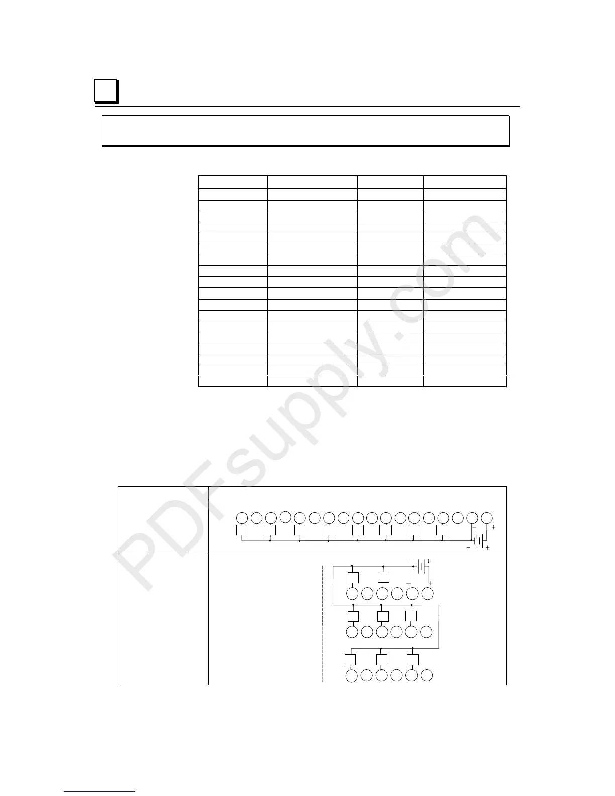
Wiring Connections
for Carriers with Two
Rows of Terminals
IC200CHS002, 005
IC200CHS012, 015
Q1
Q2 Q3 Q4 Q5 Q6 Q7
Q8
123456789 111213141516171810
B
Wiring Connections
for Carriers with Three
Rows of Terminals
IC200CHS001, 022, 025
IC200CHS011
B 123456
13
14 15 16 17 18
789 111210
Q1 Q2
Q4
Q8
Q3
Q5
Q6
Q7