GFK-1504K Chapter 9 Discrete Mixed Modules 9-9
9
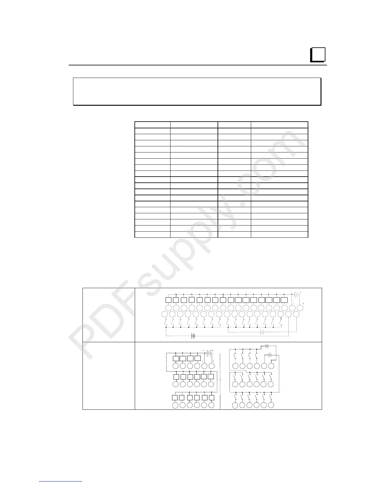
IC200MDD842
Mixed Module, Output 24VDC Pos. Logic 0.5A Grouped w/ESCP 16 Points
/ Input 24VDC Pos/Neg Logic Grouped 16 Points
Field Wiring
Terminal Connection Terminal Connection
A1 Output 1 B1 Input 1
A2 Output 2 B2 Input 2
A3 Output 3 B3 Input 3
A4 Output 4 B4 Input 4
A5 Output 5 B5 Input 5
A6 Output 6 B6 Input 6
A7 Output 7 B7 Input 7
A8 Output 8 B8 Input 8
A9 Output 9 B9 Input 9
A10 Output 10 B10 Input 10
A11 Output 11 B11 Input 11
A12 Output 12 B12 Input 12
A13 Output 13 B13 Input 13
A14 Output 14 B14 Input 14
A15 Output 15 B15 Input 15
A16 Output 16 B16 Input 16
A17 DC - B17 Inputs 1-8 Common
A18 DC + B18 Inputs 9-16 Common
The 16 outputs form one group with a DC+ and a DC- terminal. The 16 inputs form two
groups of 8. Each group has a common return. Each group may be wired for positive or
negative logic inputs. Note: Negative-logic functionality requires module version
IC200MDD842B or higher. When wiring outputs to inductive loads, use of external
suppression circuits is recommended. See chapter 2, "Installing Wiring for I/O Devices-
Wiring to Inductive Loads" for more information.
Wiring Connections
for Carriers with Two
Rows of Terminals
IC200CHS002, 005
IC200CHS012, 015
I1 I2 I3 I4 I5 I6 I7 I8 9 I10
I11 I12 I13 I14 I15 I16
Q1
Q2 Q3
Q4
Q5 Q6 Q7 Q8 Q9 Q10 Q11 Q12 Q13 Q14 Q15 Q16
123456789 1112131415161718
123456789 111213141516171810
10
B
A
+
-
(+)
(-)
-
(+)
-
(+)
+
-
(+)
(-)
Wiring Connections
for Carriers with
Three Rows of
Terminals
IC200CHS001, 022, 025
IC200CHS011
123456
13
14 15 16 17 18
789 111210
I17 I18 I19 I20 I21 I22
I23
I24
I25 I26 I27
I28
I32
+
-
(+)
-
B
I29 I30 I31
+
-
(+)
-
A
123456
13
14 15 16 17 18
7 8 9 11 1210
Q1 Q3
Q7
Q15
Q5
Q9
Q11
Q13
Q2 Q4
Q8
Q16
Q6
Q10
Q12
Q14