GFK-1504K Chapter 9 Discrete Mixed Modules 9-29
9
IC200MDD846
Mixed Module, Output Relay 2.0A per Pt Isolated 8 Points /
Input 120VAC Grouped 8 Points
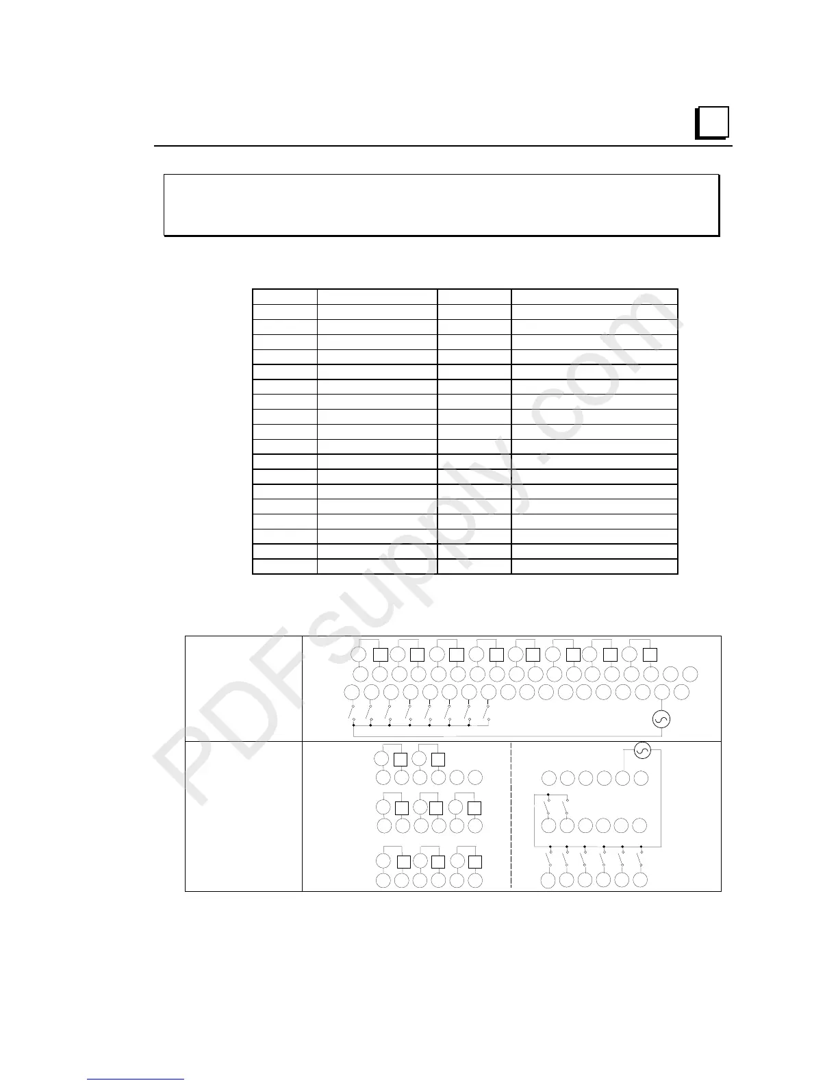
Field Wiring
Terminal Connection Terminal Connection
A1 Output 1-1 B1 Input 1
A2 Output 1-2 B2 Input 2
A3 Output 2-1 B3 Input 3
A4 Output 2-2 B4 Input 4
A5 Output 3-1 B5 Input 5
A6 Output 3-2 B6 Input 6
A7 Output 4-1 B7 Input 7
A8 Output 4-2 B8 Input 8
A9 Output 5-1 B9 No connection
A10 Output 5-2 B10 No connection
A11 Output 6-1 B11 No connection
A12 Output 6-2 B12 No connection
A13 Output 7-1 B13 No connection
A14 Output 7-2 B14 No connection
A15 Output 8-1 B15 No connection
A16 Output 8-2 B16 No connection
A17 No connection B17 Inputs 1-8 Common (Return)
A18 No connection B18 No connection
When wiring outputs to inductive loads, use of external suppression circuits is
recommended. See chapter 2, "Installing Wiring for I/O Devices-Wiring to Inductive
Loads" for more information.
Wiring Connections
for Carriers with Two
Rows of Terminals
IC200CHS002, 005
IC200CHS012, 015
Q1 Q2 Q3 Q4 Q5 Q6 Q7 Q8v v v v v v v v
I1 I2 I3 I4 I5 I6 I7 I8
N
H
1 2 3 4 5 6 7 8 9 11 12 13 14 15 16 17 18
123456789 111213141516171810
10
B
A
Wiring Connections
for Carriers with
Three Rows of
Terminals
IC200CHS001, 022, 025
IC200CHS011
123456
789 111210
A
13 14 15 16 17 18
Q4 Q5 Q6
Q7 Q8
vvv
vv
Q1 Q2 Q3
vv
v
123456
13
14 15 16 17 18
789 111210
I1 I2 I3 I4 I5 I6
I7
I8
B
NH