GFK-1504K Chapter 10 Analog Input Modules 10-11
10
IC200ALG240
Analog Input Module, 16 Bit Voltage/Current, 1500VAC Isolation, 8 Channels
Field Wiring
Number Connection Number Connection
A1 Shield Termination Point B1 Shield Termination Point
A2 VIN1- B2 VIN5-
A3 IIN1- B3 IIN5-
A4 VINIIN1+ B4 VINIIN5+
A5 Shield Termination Point B5 Shield Termination Point
A6 VIN2- B6 VIN6-
A7 IIN2- B7 IIN6-
A8 VINIIN2+ B8 VINIIN6+
A9 Shield Termination Point B9 Shield Termination Point
A10 VIN3- B10 VIN7-
A11 IIN3- B11 IIN7-
A12 VINIIN3+ B12 VINIIN7+
A13 Shield Termination Point B13 Shield Termination Point
A14 VIN4- B14 VIN8-
A15 IIN4- B15 IIN8-
A16 VINIIN4+ B16 VINIIN8+
A17 DC- B17 No connection
A18 DC+ B18 No connection
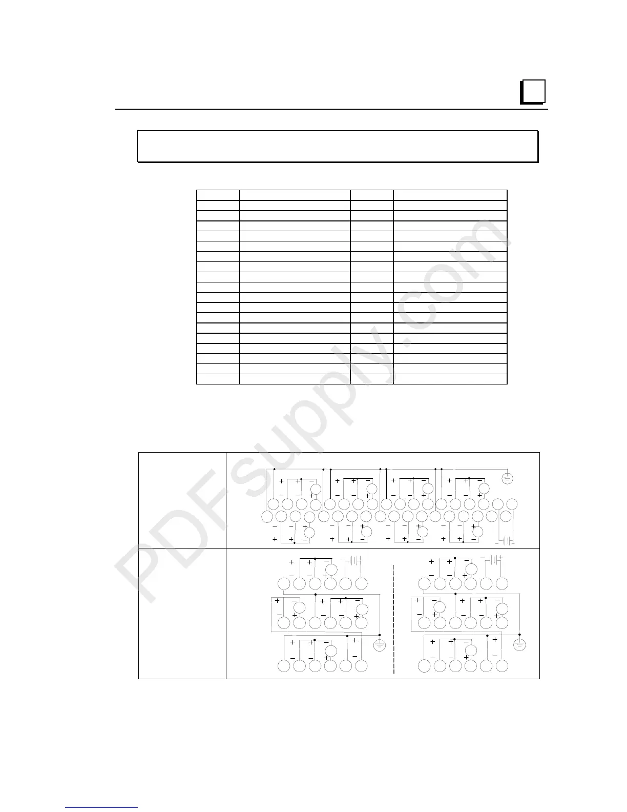
A 24 volt power supply must be connected to A17 and A18 to operate the module. The
power wiring does not require shielding. Current inputs are applied with positive current
flow into VININn+ and out of IINn-. Both negative terminals IINn- and VINn- of the
channel should be connected together for best accuracy on current ranges. Voltage inputs
are applied between VININn+ and VINn- with positive to VININn+.
Wiring Connections
for Carriers with Two
Rows of Terminals
IC200CHS002, 005
IC200CHS012, 015
Shield Connections
I5
VI
AI1
VI
I4
V
I
I2
VI
I3
V
I
AI6
V
I
AI7
VI
I8
VI
123456789 1112131415161718
123456789 111213141516171810
10
B
A
Wiring Connections
for Carriers with
Three Rows of
Terminals
IC200CHS001, 022, 025
IC200CHS011
123456
789 111210
A
13 14 15 16 17 18
123456
13 14 15 16 17 18
B
7 8 9 11 1210
AI1
VI
V
AI2
I
AI3
V
I
AI4
V
I
AI5
VI
V
AI6
I
AI7
V
I
AI8
V
I