10-34 VersaMax® Modules, Power Supplies, and Carriers User's Manual – March 2003 GFK-1504K
10
IC200ALG262
Analog Input Module, 15 Bit Differential Current 8 Channels
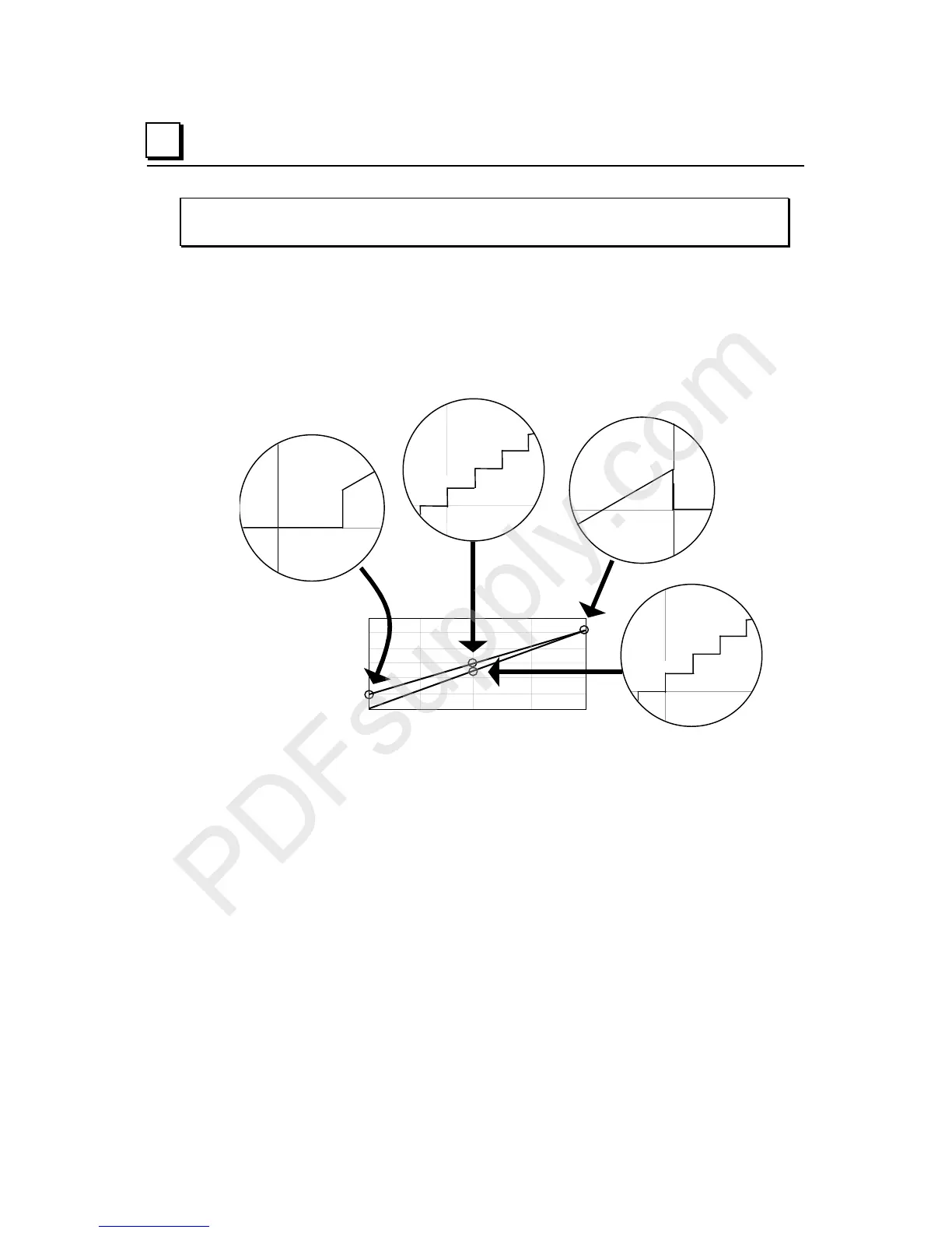
Scaling
The illustration below shows the relationship between the input current measured at the
field terminals and the data that is output by the module.
Count and 4-20mA Input Current
12.1935mA
0 8192 16384 24576 32767
Count
24
20
16
12
8
4
0
mA
12.1925mA
12.193mA
16386
16385
16384
12.192mA
0.5µA = 1counts
10.241875mA
10.240625mA
10.24125mA
16386
16385
16384
10.240mA
0.625µA = 1counts
0-20mA Range
4-20mA Range
Note 2) 4-20mA Range
20.000mA
32000
20.3835mA
32767
20.384mA
32000
Note 1) 4-20mA Range
4.000mA
0
4.077mA
154
4.0765mA
0
The following equations can be used to calculate count values:
4-20mA Range: Counts = ( Current in mA - 4mA) x (32000 / 16mA
)
0-20mA Range: Counts = ( Current in mA ) x (32000 / 20mA
)
Note 1) In 4-20mA mode, signal inputs below 4.077mA are converted to zero counts.
Note 2) In 4-20mA mode, signal inputs at 20.000mA or above 20.383mA are converted to 32000
counts.
The count value must be a multiple of 4. If the module receives a count value that is not a multiple
of 4, It rounds the value down to the closest multiple of 4. For example, in 4-20mA mode:
Count mA
16000 12.000
16003 12.000
16004 12.002