11-36 VersaMax® Modules, Power Supplies, and Carriers User's Manual – March 2003 GFK-1504K
11
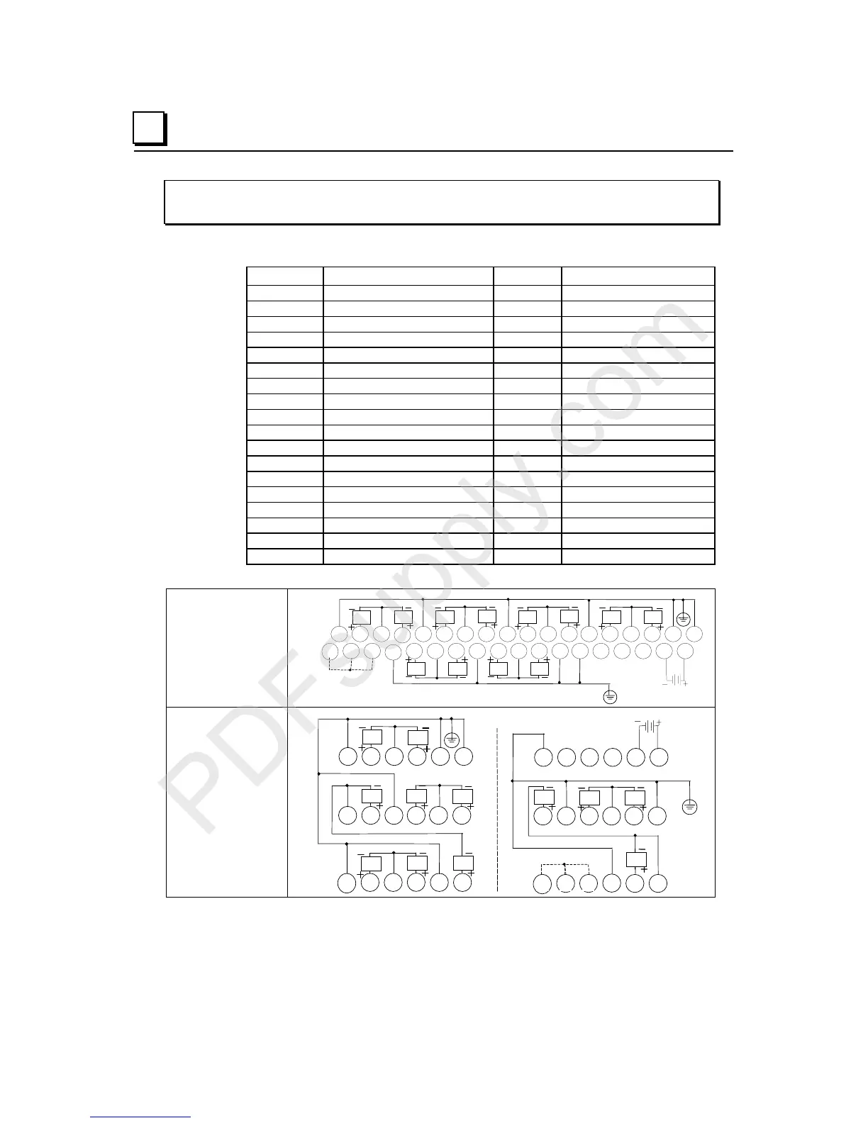
IC200ALG327
Analog Output Module, 13 Bit Voltage 12 Channels
Field Wiring
Terminal Connection Terminal Connection
A1 Shield Termination Point B1 JMP 1 (Range)
A2 V OUT 5 B2 Jumper (1-2) RTN
A3 RET (5-6) B3 JMP 2 (Hold)
A4 V OUT 6 B4 Shield Termination Point
A5 Shield Termination Point B5 V OUT 1
A6 V OUT 7 B6 RTN (1-2)
A7 RTN (7-8) B7 V OUT 2
A8 V OUT 8 B8 Shield Termination Point
A9 Shield Termination Point B9 V OUT 3
A10 V OUT 9 B10 RTN (3-4)
A11 RTN (9-10) B11 V OUT 4
A12 V OUT 10 B12 Shield Termination Point
A13 Shield Termination Point B13 Shield Termination Point
A14 V OUT 11 B14 No connection
A15 RTN (11-12) B15 No connection
A16 V OUT 12 B16 No connection
A17 Shield Termination Point B17 Field Return
A18 Shield Termination Point B18 Field Power
Wiring Connections
for Carriers with Two
Rows of Terminals
IC200CHS002, 005
IC200CHS012, 015
1 2 3 4 5 6 7 8 9 11 12 13 14 15 16 17 18
1 2 3 4 5 6 7 8 9 11 12 13 14 15 16 17 1810
10
B
A
AQ7AQ6
AQ5
AQ8
AQ12
AQ11
JMP1 JMP2
AQ4
Shield Connections
AQ3
AQ9
AQ10
AQ2AQ1
Wiring Connections
for Carriers with
Three Rows of
Terminals
IC200CHS001, 022, 025
IC200CHS011
AQ4
A
123
13
14 15 16
789 111210
456
Shield Connections
B
1 2 3
13
14 15 16 17 18
7 8 9 11 1210
JMP1
456
17 18
JMP2
AQ2
AQ3
AQ1
AQ7AQ6
AQ5
AQ10
AQ9AQ8
AQ12
AQ11
 Loading...


