GFK-1504K Chapter 11 Analog Output Modules 11-35
11
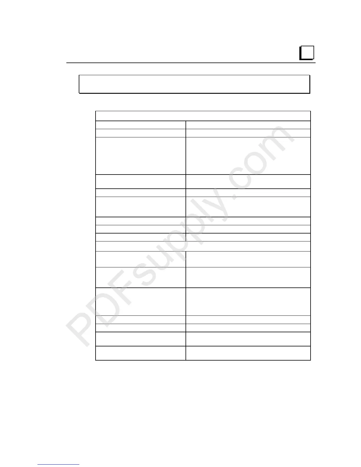
IC200ALG327
Analog Output Module, 13 Bit Voltage 12 Channels
Module Specifications
Module Characteristics
Channels 12 single-ended, one group
Module ID FFFF90C0
Isolation:
User input to logic (optical) and
to frame ground
Group to group
Channel to channel
250VAC continuous; 1500VAC for 1 minute
Not applicable
None
LED indicators FLD PWR LED indicates field power is present
OK LED indicates backplane power is present
Backplane current consumption 5V output: 50mA maximum
External power supply:
Range
Current consumption
+18 to +30VDC (including ripple)
112mA maximum
Thermal derating None
Configuration parameters Range, output default
Diagnostics Loss of User Side Power
Output Characteristics
Output voltage -10.24 to +10.24VDC (bipolar range)
0 to +10.24VDC (unipolar range)
Load characteristics:
Resistive
Capacitive
5000 Ohms minimum
1.0µF maximum
Accuracy:
at 25 degrees C
0 to 60 degrees C
+/- 0.3% typical of full scale, +/- 0.5% maximum of
full scale
+/-1% maximum of full scale
Resolution 1.25mV = 4 counts
Update rate per module 15 mSec maximum
Channel-to-channel crosstalk
rejection
70dB minimum
Output default Hold Last State (default)
0V (configurable)

 Loading...


