11-46 VersaMax® Modules, Power Supplies, and Carriers User's Manual – March 2003 GFK-1504K
11
IC200ALG328
Analog Output Module, 13 Bit Current, 12 Channels
Output Current Range Scaling / Step Change
In 0-20mA range mode, a current output signal value of 0mA corresponds to a %AQ value
of 0 counts, and 20mA corresponds to a %AQ value of +32,000 counts. In 4-20mA range
mode, a value of 0 %AQ counts corresponds to an output current of 4mA and a value of
+32,000 %AQ counts corresponds to an output current of 20mA. If the module is installed
in a Versamax PLC, it converts negative value commands to 0 mA regardless of range
selected. If the module is controlled by a Network Interface Unit (NIU), it converts any
negative value commands to the low end of range.
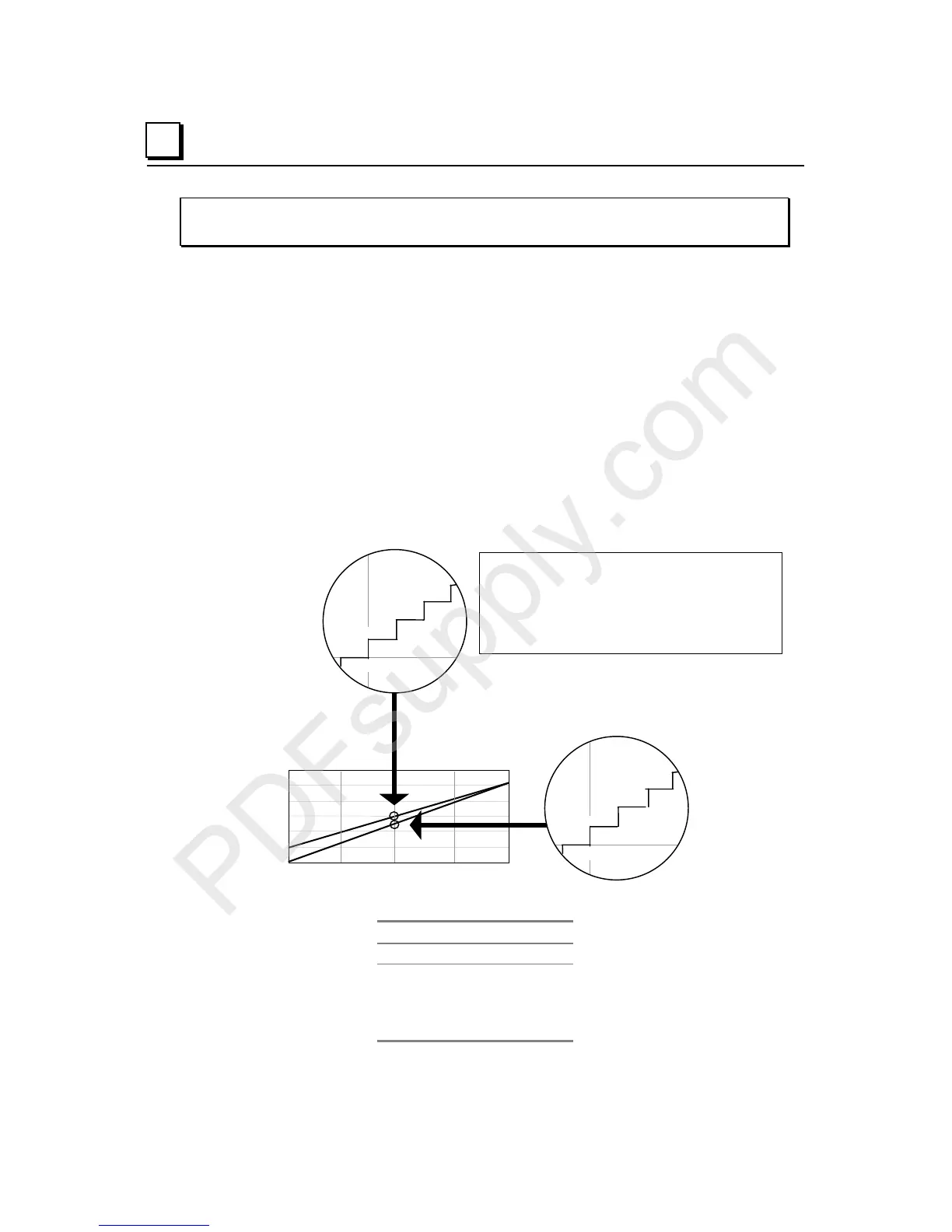
The illustration below shows the relationship between output signal strength and
commanded %AQ counts. It depicts the step change in output current level for various
command values. Not every command value results in a change in the output current level
due to the module’s resolution.
12.0075mA
0 8000 16000 24000 32767
%AQ Count
24
20
16
12
8
4
0
mA
12.0025mA
12.005mA
16015
16010
16005
12.000mA
2.
A =
nt
10.0075mA
10.0025mA
10.005mA
16012
16008
16004
10.000mA
2.5
A = 4 counts
0-20mA Range
4-20mA Range
For 4-20mA range:
Current (in mA) = 4 + (16)*(%AQ counts / 32000)
%AQ counts = (2000)*(Current (in mA) – 4)
For 0-20mA range:
Current (in mA) = (20)*(%AQ counts / 32000)
%AQ counts = (1600) * Current (in mA)
4-20 mA Range Step Change Example
Count Current
16000 12.0000 mA
16005 12.0025 mA
16008 12.0025 mA
16009 12.0025 mA
16010 12.0050 mA