11-56 VersaMax® Modules, Power Supplies, and Carriers User's Manual – March 2003 GFK-1504K
11
IC200ALG331
Analog Output Module, 16 Bit Voltage/Current, 1500VAC Isolation, 4 Channels
Scaling Example
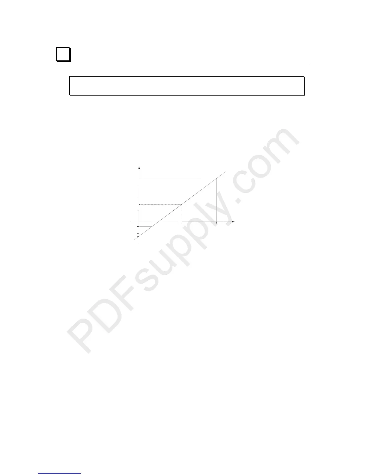
A channel is configured in the 0 to 10 volts DC range. It measures a velocity output.
Electronic sensors and mechanical linkage external to the module have determined that an
output level of +1.5 volts DC is equal to –20 feet/second (–6 meters/second), and that +9
volts DC is equal to +180 feet/second (+50 meters/second). Plotting these values on a
graph shows that a signal of 5 volts DC corresponds to a speed of 73.3 feet/second.
+10.0+5.0 +9.0
Velocity
Output
Voltage
200
100
50
150
-50
-20
-60
(+1.5V, -20 ft/sec)
(+9.0V, +180 ft/sec)
For engineering units of feet per second, the following scaling values are used:
Low engineering units = –20 ft/sec
High engineering units = +180 ft/sec
Low span units = 1500 millivolts
High span units = 9000 millivolts
An output value of 5.0 volts would be scaled to an engineering value of +00073 (ft/sec).
In this example, scaling to hundredths of feet per second would provide better resolution.
The following scaling values would be used:
Low engineering units = –2000 hundredths ft/sec
High engineering units = +1800 hundredths ft/sec
Low span units = 1500 millivolts
High span units = 9000 millivolts
An output value of 5.0 volts would be scaled to an engineering value of +7333 (hundredths
of ft/sec).