GFK-1504K Chapter 13 Mixed Discrete/High-speed Counter Module 13-9
13
IC200MDD841
Mixed Module, 24VDC Positive Logic Input 20 Points / Output 12 Point /
(4) High Speed Counter, PWM, or Pulse Train Configurable Points
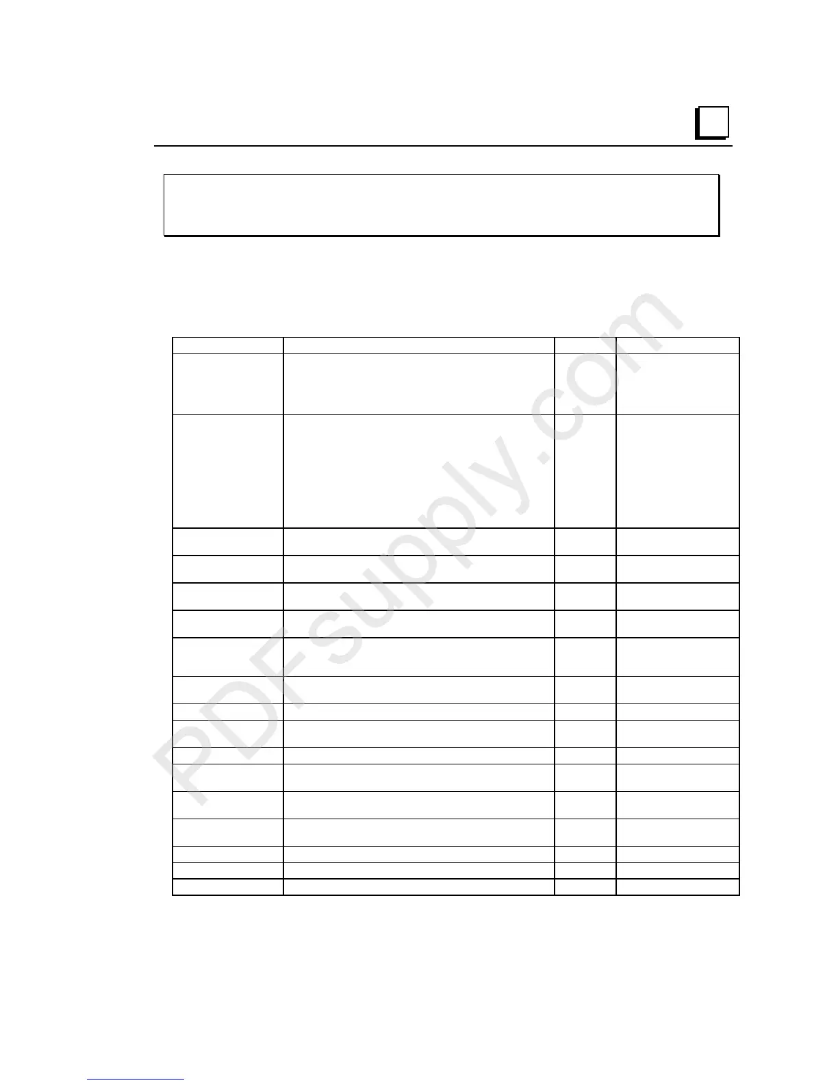
Configurable
Features
The default parameters of this module can be used in many applications. The module can
be software-configured when it is installed in a VersaMax PLC system, or an I/O Station
controlled by a Network Interface Unit that provides software configuration.
Parameter Description Default Setting/Value Range
Counter Type Specifies the counter configuration. If 1 Type B & 2 Type A is
selected, counter #1 parameters are used for the Type B
counter (except Counter #1 Direction and Counter #1 Count
Input Edge parameters) and counter #4 parameters are used
for the Type A counter.
4 Type A 4 Type A counters,
1 Type B & 2 Type A,
1 Type B2
Output Stop Mode
Defines what outputs do if the system is in stop mode. Normal
means that HSC outputs continue to respond to the counter
inputs and standard outputs turn off. Preset outputs, continue
to operate as if the CPU/NIU were present, changing state to
reflect the counter Accumulators.
Force Off means all Preset outputs are turned off and remain
off until the CPU/NIU returns to normal operation.
Hold Last means Preset outputs retain current levels and do
not reflect the counter Accumulators.
Normal Normal, Force All Outputs
Off, Hold
Channel #1/2/3/4
Function
Specifies channel function. HSC HSC, PWM, Pulse Train,
Standard, Ramp
Counter Output
#1/2/3/4 Enable
Specifies if the counter output is enabled. If disabled, the
output is used as a standard output.
Enabled Enabled, Disabled
Counter #1/2/3/4
Direction
(Type A only). Specifies whether count inputs increment or
decrement the accumulator.
Up Up, Down
Counter #1/2/3/4 Mode Defines whether the counter wraps if the count limit is reached
(continuous) or if it stops at the counter limit.
Continuous Continuous , Single Shot
Counter #1/2/3/4
Preload/Strobe
Selection
Specifies the function of the Preload/Strobe Input. Preload Preload, Strobe
Counter #1/2/3/4 Count
Input Edge for Type A
For Type A counters only, specifies which transition of this
input is used. Positive is a low-to-high transition.
Positive Positive, Negative. Type B
and B2 always positive.
Time Base #1/2/3/4 Specifies the timebase for the Counts-per-Timebase register. 1000mS 10mS to 65530mS
High Limit #1/2/3/4 Defines the counter’s upper limit. It must be greater than the
low limit
+32,767 -32,767 to +32,767
Low Limit #1/2/3/4 Defines the counter’s lower limit. 0 -32,768 to +32,766
ON Preset #1/2/3/4 Defines the counter’s ON preset. When the count is at or
above this value, the HSC output is turned on.
+32,767 -32,768 to +32,767
OFF Preset #1/2/3/4 Defines the counter’s OFF preset. When the count is at or
above this value, the HSC output is turned off.
0 -32,768 to +32,767
Preload Register
#1/2/3/4
This register value is the Preload value for the counter. 0 -32,768 to +32,767
Home Value The Home Value for the counter. 0 -32,768 to +32,767
Acceleration Pulse Train acceleration rate from stop to full speed. 1,000,000 10 to 1,000,000
Deceleration Pulse Train deceleration rate from full speed to stop. 1,000,000 10 to 1,000,000

 Loading...


