4-10 VersaMax® Modules, Power Supplies, and Carriers User's Manual – March 2003 GFK-1504K
4
IC200CHS003
Connector-Style I/O Carrier
Field Wiring Connection
I/O devices can be wired directly to Interposing I/O Terminals, described separately in this
chapter, or other types of terminal strips.
Connection to the Connector Style I/O Carrier is made by cable. The following cables are
available:
IC200CBL105 2 connectors, 0.5m, no shield
IC200CBL110 2 connectors, 1.0m, no shield
IC200CBL120 2 connectors, 2.0m, no shield
IC200CBL230 1 connector, 3.0m, no shield
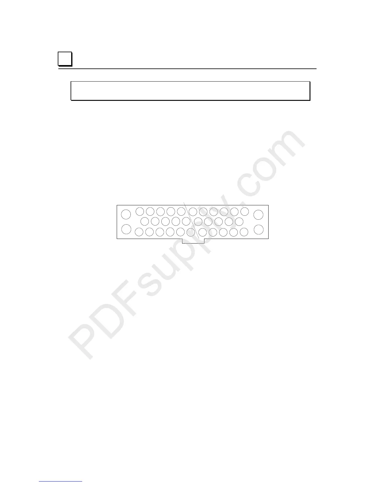
The notch on the connector indicates the orientation of the pins.
A1 A2 A3
A4
A5 B5 B6 B3 B4 B1 B2
A6 A7 A8
A9
A10 B12 B9 B10 B7 B8
A11 A12 A13
A14
A15 A16 B15 B16 B13 B14 B11
B17
B18
A17
A18
A connector kit is available for building custom cables. The kit is part number
IC200ACC304.
The carrier accommodates current levels up to 2 Amps per point or 8 Amps per each
power and ground, and a voltage range of up to 264 VAC. Voltage transients up to 300
VAC will not damage the carrier.
Compatiblity
This carrier can be used with all VersaMax I/O modules EXCEPT the following, due to
their high isolation requirements:
IC200MDL144 Input 240VAC 4 Point Isolated Module
IC200MDL244 Input 240VAC 8 Point Isolated Module
IC200MDD850 Mixed 240VAC Isolated 4 Point / Output Relay 2.0A
Isolated 8 Point Module