177
2. SPEEDOMETER MALFUNCTION
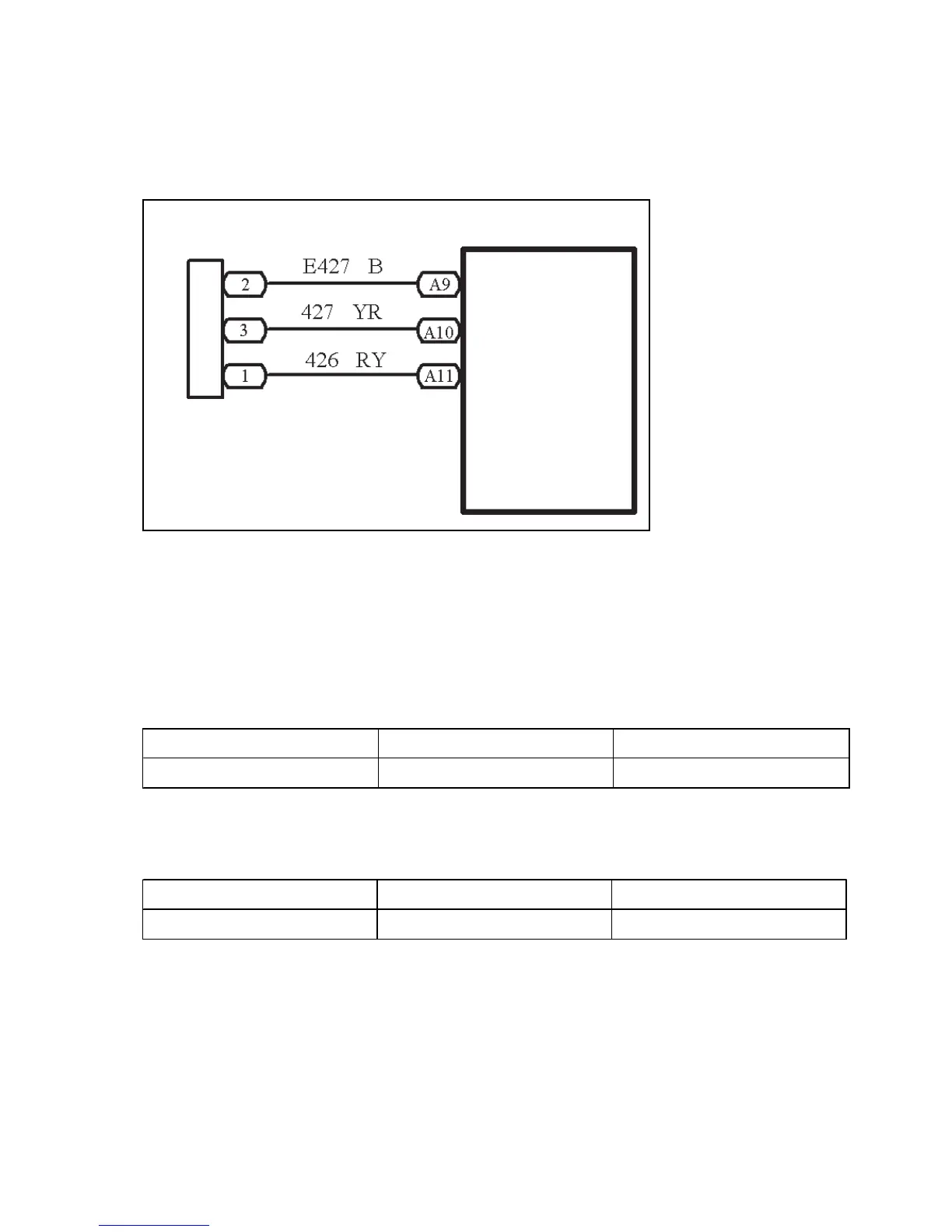
CIRCUIT DIAGRAM
INSPECTION
(a) Inspect the combination meter assembly
1 Remove the combination meter assembly and retain the connection of connectors.
2 Inspect continuity
Inspect continuity between terminals
Standard:
3 Inspect voltage between terminals
Standard:
Result and solution:
If it is abnormal, go to (b) Inspect the combination meter assembly speed input signal
If normal, go to (c) Inspect the combination meter assembly
Tester connection Condition Standard condition
A9 - ground Normal condition Continuity
Speedometer Sensor
Combined Meter Assembly
Ground the
Speedometer Sensor
Speedometer Sensor+8V
Power Source
Speed Signal
Tester connection Condition Standard condition
A10 - ground Turn the ignition switch to ON 7.5 – 9V
 Loading...