The frequency reference command is set via the RS-485 communication port using the MODBUS RTU proto-
col.
Refer to parameter group 9 for additional information.
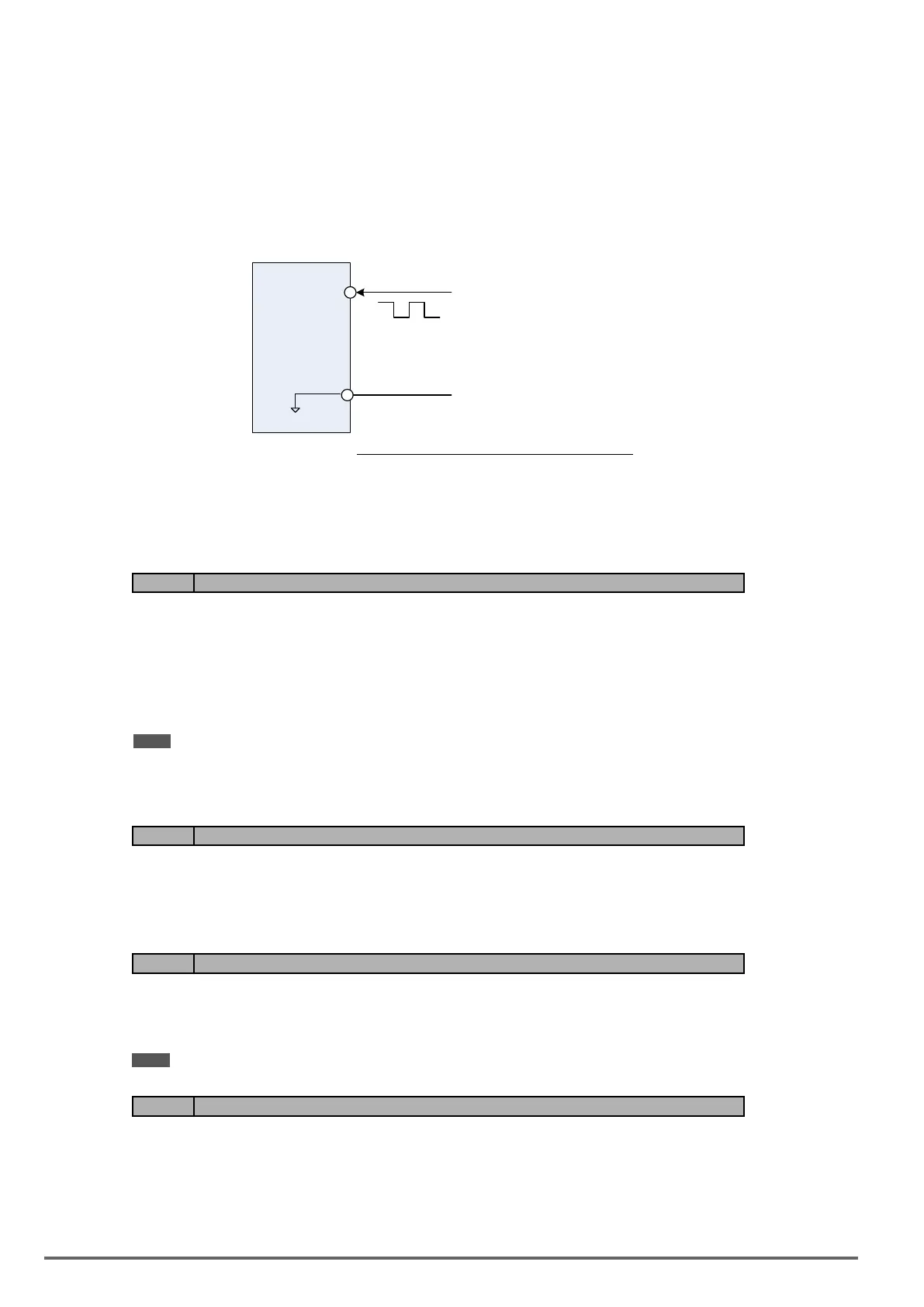
00-05/00-06=4:Pulseinput
To use this function a pulse train input is required to be connected to the PI input and GND (see g. 4.4.5).
Set parameter 03-30 to 0 to use the pulse input as frequency reference. Refer to parameters 03-31 to 03-34 for
pulse input scaling.
PI input terminal, built-in resistance, is not required to connect the resistance if open collector input mode is
used.
PI
GND
0V
(Internal resistence : 3.89 K)
Serial pulse input
Specification
Low Input Level: 0.0 to 0.5 V
High Input Level: 4.0 to 13.5 V
Duty cycle: (ON / OFF) 30 % to 70%
Pulse Input frequency range: 50 to 32 KHz
Figure4.4.5Frequencyreferencefrompulseinput
00-05/00-06=7:AI2AuxiliaryFrequency
When 04-05 is set to 0 (auxiliary frequency), frequency command is provided by multi-function analog input AI2
and the maximum output frequency (01-02, Fmax) = 100%.
When 04-05 is not set to 0, the frequency is 0. Refer to p4-76 for multi-speed descriptions.
Code Parameter Name / Range
00-07 Main and Alternative Frequency Command modes
0: Main frequency
1: Main frequency + alternative frequency
When set to 0 the reference frequency is set by the main reference frequency selection of parameter 00-05.
When set to 1 the reference frequency is sum of the main reference frequency (00-05) and alternative frequen-
cy (00-06).
Note: The inverter will display the SE1 error when 00-07 = 1 and parameter 00-05 and 00-06 are set to the same selection.
When parameter 00-06 is set to 0 (Keypad) the alternative frequency reference is set by parameter 05-01 (Fre-
quency setting of speed-stage 0).
Code Parameter Name / Range
00-08 Communication frequency command – READ ONLY
0.00~599.00 Hz
Display the frequency reference when 00-05 or 00-06 is set to communication control (3).
Code Parameter Name / Range
00-09 Communication frequency command memory
0: Don’t save when power supply is off. (00-08)
1: Save when power is off. (00-08)
Note: This parameter is only enabled in communication mode.
Code Parameter Name / Range
00-10 Minimum frequency detection
0: Show warning if lower than minimum frequency
1: Run as minimum frequency if lower than minimum frequency
00-10=0: Frequency command is lower than 01-08 (Minimum Output Frequency of Motor 1), it shows STP0
warning.
100 VDI100 • Instruction manual

 Loading...


