Note: It will not restore to the default value when this parameter performs initialization.
Code Parameter Name / Range
00-05 Main Frequency Command Source Selection
00-06 Alternative Frequency Source Selection
0: Keypad
1: External control (analog)
2: Terminal UP / DOWN
3: Communication control
4: Pulse input
5: Reserved
6: Reserved
7: AI2 Auxiliary Frequency
00-05/00-06=0:Keypad
Use the digital operator to enter frequency reference or to set parameter 05-01 (frequency reference 1) as
alternative frequency reference source. Refer to section 4.1.4 for details.
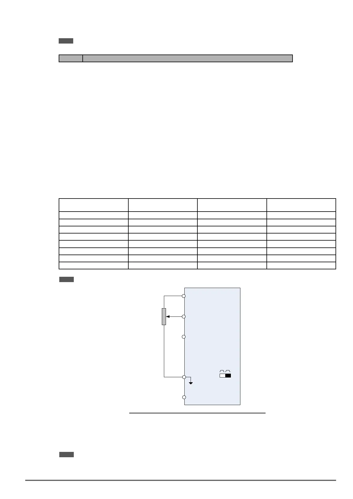
00-05/00-06=1:Externalcontrol(AnalogInput)
Use analog reference from analog input AI1 or AI2 to set the frequency reference (as shown in Figure 4.4.4).
Refer to parameters 04-00 to select the signal type.
AI1 – Analog Input 1 AI2 – Analog Input 2 04-00 Setting
(Default = 1)
Dipswitch SW2
(Default ‘V’)
0 ~ 10V 0 ~ 10V 0 Set to ‘V’
0 ~ 10V 4 ~ 20mA 1 Set to ‘I’
-10 ~ 10V 0 ~ 10V 2 Set to ‘V’
-10 ~ 10V 4 ~ 20mA 3 Set to ‘I’
0 ~ 12V 0 ~ 12V 4 Set to ‘V’
0 ~ 12V 4 ~ 20mA 5 Set to ‘I’
-12 ~ 12V 0 ~ 12V 6 Set to ‘V’
-12 ~ 12V 4 ~ 20mA 7 Set to ‘I’
Note: Set parameter 04-05 to 10 to add frequency reference using AI2 to AI1.
+10V
GND
SW2
I
V
-10V
2K
Ω
AI1
AI2
Main Speed
Frequency Reference
Command
(Voltage Input)
Main Speed
Frequency Reference
Command
(Current Input)
Figure4.4.4Analoginputasmainfrequencyreferencecommand
00-05/00-06=2:TerminalUP/DOWN
The inverter accelerates with the UP command closed and decelerates with the DOWN command closed.
Please refer to parameter 03-00 ~ 03-07 for additional information.
Note: To use this function both the UP and DOWN command have to be selected to any of the input terminals.
00-05/00-06=3:Communicationcontrol
VDI100 • Instruction manual 99

 Loading...


