03-27=3:
Keep the state of frequency command not to be cleared. When run command re-sends, press UP/DOWN key
before the run frequency reaches the frequency command.
Code Parameter Name / Range
03-40 Up/Down Frequency Width Setting
0.00~5.00 Hz
When 03-40 is set to 0 Hz, Up / Down function is maintained.
When 03-40 is not set to 0 Hz, frequency command is set by the run frequency plus the setting frequency of
03-40.
Example: set terminal S1: 03-00=8 (Up increased frequency command), terminal S2: 03-01=9 (Down de-
creased frequency command) and 03-40= ∆Hz.
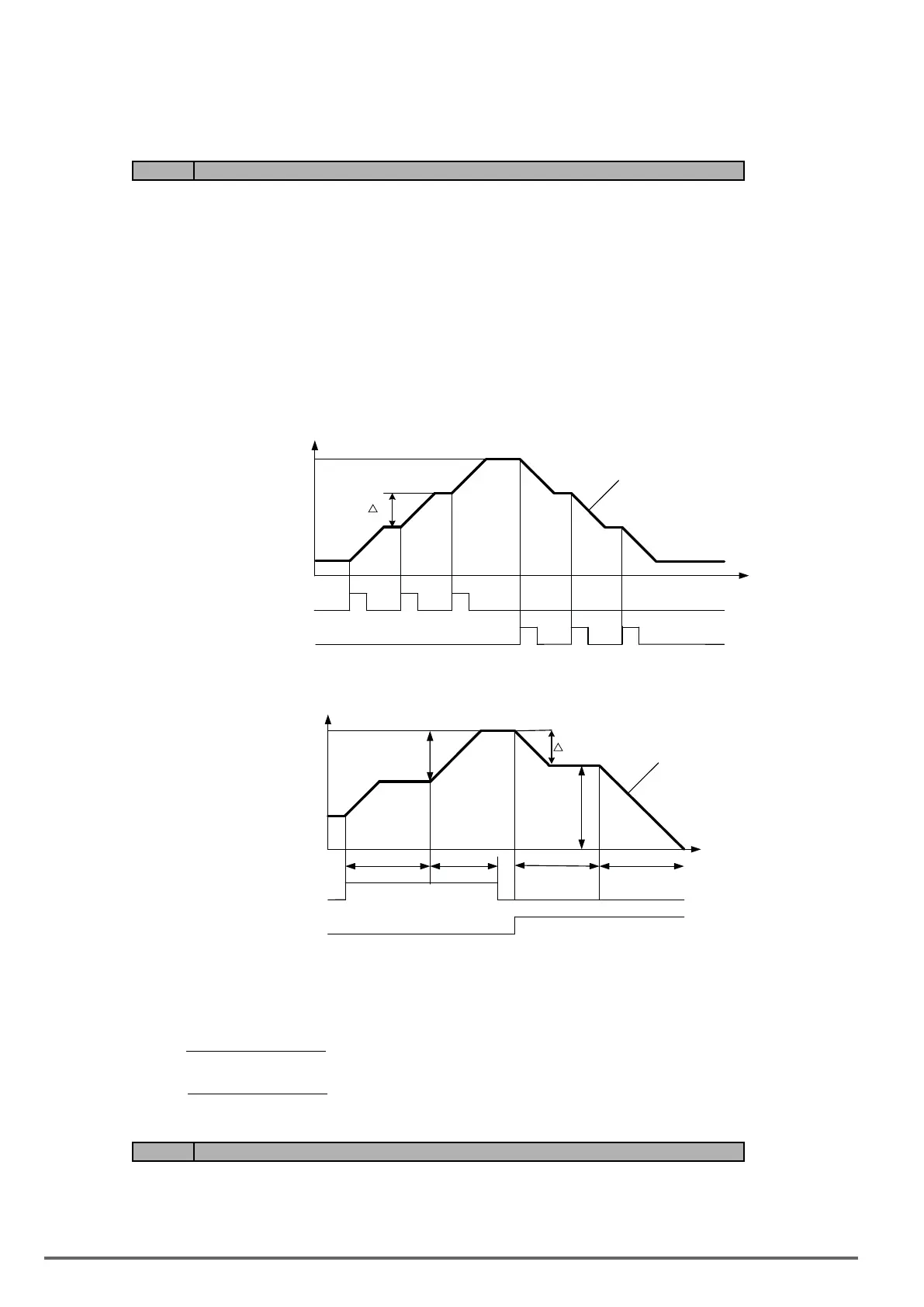
Mode 1: When 03-40 is set to 0 Hz, Up / Down function is maintained. Refer to Fig. 4.4.20.
Mode 2: When 03-40 is not set to 0 Hz and terminals conduction time < 2 s, frequency change (∆Hz) at one
conduction occurs depending on the setting of 03-40.
Terminal S1
Terminal S2
ON ON ON
Hz
T
△Hz
Output
Frequency
ON ON ON
Lower
Limit of
Frequency
Reference
Upper
Limit of
Frequency
Reference
Mode 3: When 03-40 is not set to 0 Hz and terminals conduction time > 2 s, frequency changes upon general
acceleration/ deceleration.
Terminal S1
Terminal S2
ON
2Sec
OFF
OFF
ON
2Sec
T
Hz
Upper
Limit of
Frequency
Reference
Output
Frequency
DH1
t1
DH2
t2
△Hz
Lower
Limit of
Frequency
Reference
Descriptions:
∆H1: frequency increment setting at acceleration, t1: terminal conduction time at acceleration,
∆H2: frequency increment setting at deceleration, t2: terminal conduction time at deceleration.
(t1) Time Conduction Terminal
2 Time onAccelerati
Frequency Limit Upper
ΔH1 ×=
(t2) Time Conduction Terminal
2 Time onDecelerati
Frequency Limit Lower
ΔH2 ×=
Code Parameter Name / Range
03-28 Photo-coupler Output
See function selection list parameter 03-11
03-29 Photo-coupler Output Selection
164 VDI100 • Instruction manual

 Loading...


