xxx0b: Photo-coupler A Contact
xxx1b: Photo-coupler B Contact
0 = Normally open (A), 1 = Normally closed (B)
Code Parameter Name / Range
03-30 Function setting of pulse input
0: General Pulse Input
1: PWM
There are two ways for pulse input selection:
(1) General pulse input:
PI= cutoff frequency divided by pulse input scale set by 03-31, corresponding to the maximum output fre-
quency of motor 1 (01-02).
Monitoring parameter 12-79 (pulse input percentage) is the proportional relationship between input signal
and pulse input scale of 03-31.
(2) PWM: It is required to input the correct frequency.
PWM= Time of negative edge pulse divided by the time period of pulse, corresponding to the maximum
output frequency of motor 1 (01-02).
Monitoring parameter 12-79 (pulse input percentage) is the proportional relationship between the negative
edge terminal of input signal and time period.
Note: Deviation of pulse time period in PWM is ±12.5%. If it is over the deviation range, pulse input is not active.
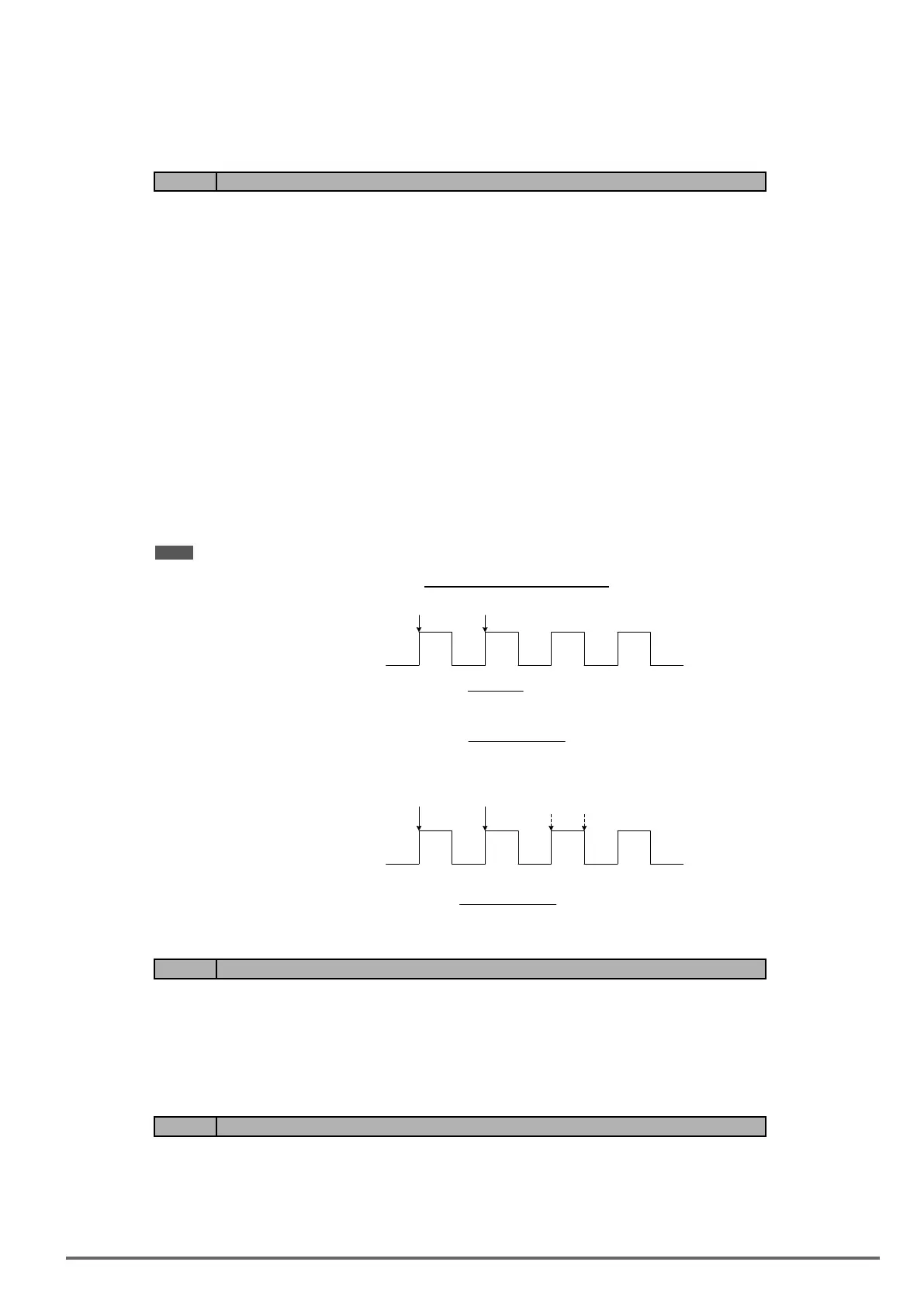
Diagramforpulseinputselection:
PI
Normal Mode
Sample
Pulse train
T:Period
1
T:Period
Frequency =
PI
Sample
Pulse train
T1:Period
T:Period
03-30 = 1
PWM Mode
Scaling factor
(using 03-31)
Pulse Input Command =
Frequency
T:Period
Pulse Input Command =
T1:Period
x 100%(01-02)
x 100%(01-02)
Code Parameter Name / Range
03-31 Scale of pulse input
Depending on the setting of 03-30
03-30=0: 50~32000Hz
03-30=1: 10~1000Hz
Pulse input scaling, 100% = Maximum pulse frequency.
Code Parameter Name / Range
03-32 Pulse input gain
0.0~1000.0 %
Target value (03-03) in % = Pulse input frequency scaled to 100% based on maximum pulse frequency (03-31)
times the gain (03-32) + bias (03-33).
VDI100 • Instruction manual 165

 Loading...


