Code Parameter Name / Range
03-33 Pulse input bias
-100.0~100.0 %
Target value (03-03) in % = Pulse input frequency scaled to 100% based on maximum pulse frequency (03-31)
times the gain (03-32) + bias (03-33).
Code Parameter Name / Range
03-34 Pulse input filter time
0.00~2.00 s
* Refer to section 3.9 control circuit terminals for details.
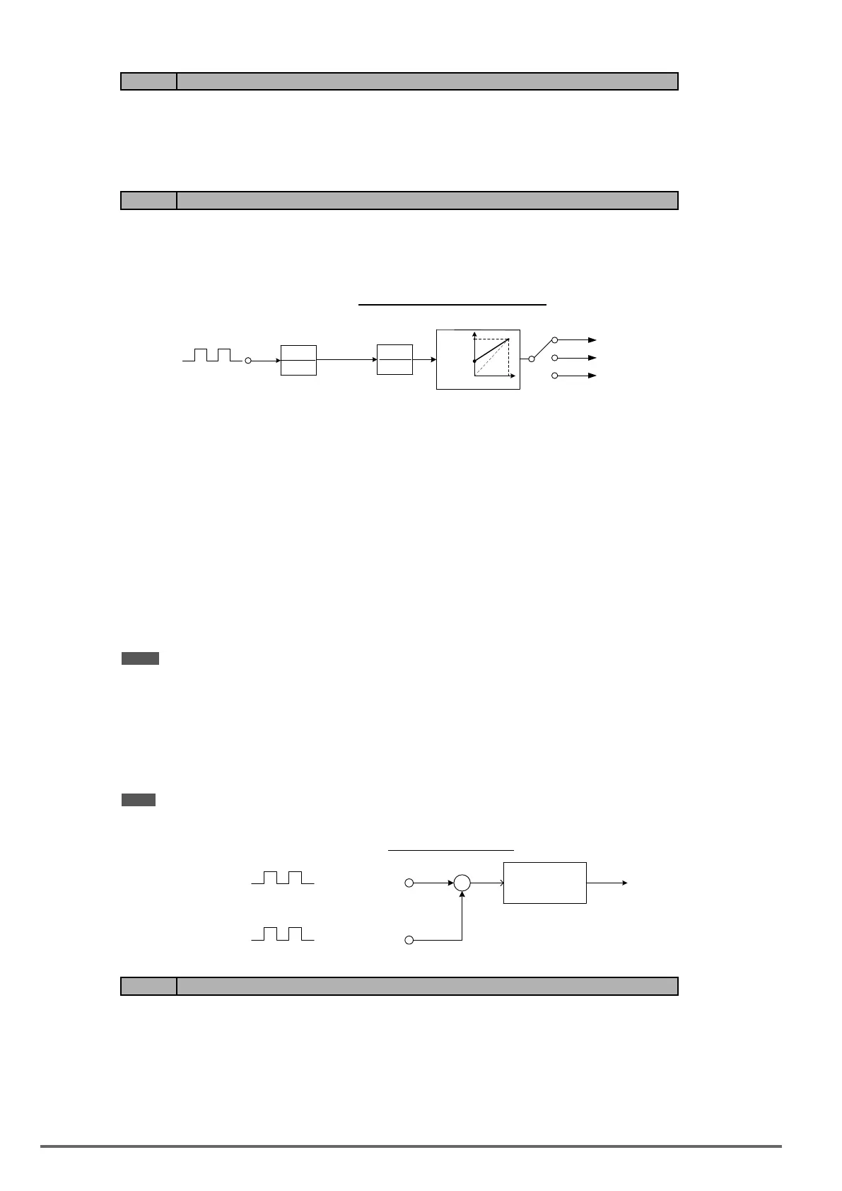
* Refer to gure 4.4.27 for the pulse input specication.
Figure4.4.27Pulseinputadjustment
1+ST
1
PI
K
1
03-32
03-33
0% 10%
Filter
Scaling
03-30 = 0
03-30 = 1
03-30 = 2
Frequency Reference
PID Feedback
PID Target
K: Scaling factor
(Using 03-31)
T: Pulse input filter
time (using 03-34)
Pulse
train
Set Pulse Input Setup as Frequency Reference
Set parameter 00-05 to 4 and 03-30 to 0 to use the pulse input terminal PI as the frequency reference source.
Refer to Figure 4.3.5. for details. Next set the pulse input scaling (03-31), enter the pulse input frequency to
match the maximum output frequency. Adjust the pulse input lter time in case interference or noise is encoun-
tered.
Example: Pulse train input maximum 10 kHz, set parameter 03-31 to 10000 when maximum frequency is set to
60.0Hz.
Set Pulse Input as PID feedback value
Set parameter 00-05 to 5, 03-30 to 1 and PID feedback value source 10-01 to 3, to use the pulse input terminal
PI as the PID target (setpoint) value. Next set the pulse input scaling (03-31), enter the pulse input frequency to
match the maximum output frequency. Adjust the pulse input lter time in case interference or noise is encoun-
tered. Refer to Figure 4.4.28.for details.
Note: The inverter will display a SE09 “PI setting error” when 03-30 = 1 and 10-01 is not set to 3.
Set Pulse Input as PID target value
Set parameter 00-05 to 5 and 03-30 to 2 to use the pulse input terminal PI as the PID target (setpoint) value.
Next set the pulse input scaling (03-31), enter the pulse input frequency to match the maximum output fre-
quency. Adjust the pulse input lter time in case interference or noise is encountered. Refer to Figure 4.4.28.for
details.
Note: The inverter will display a SE09 “PI setting error” if 03-30=0 and PID control is enabled (10-03 > 0).
Figure4.4.28PIDcontrol
PID
Regulator
Target value
+
-
Frequency
Reference
Feedback value
Pulse
train
03-30=2
03-30=1
Setpoint
Code Parameter Name / Range
03-35 Function setting of pulse output
1: Frequency command
2: Output frequency
3: Output frequency after the soft start
4: Motor speed
5: PID feedback
6: PID input
7: PG output (with PG card)
166 VDI100 • Instruction manual

 Loading...


