Application examples
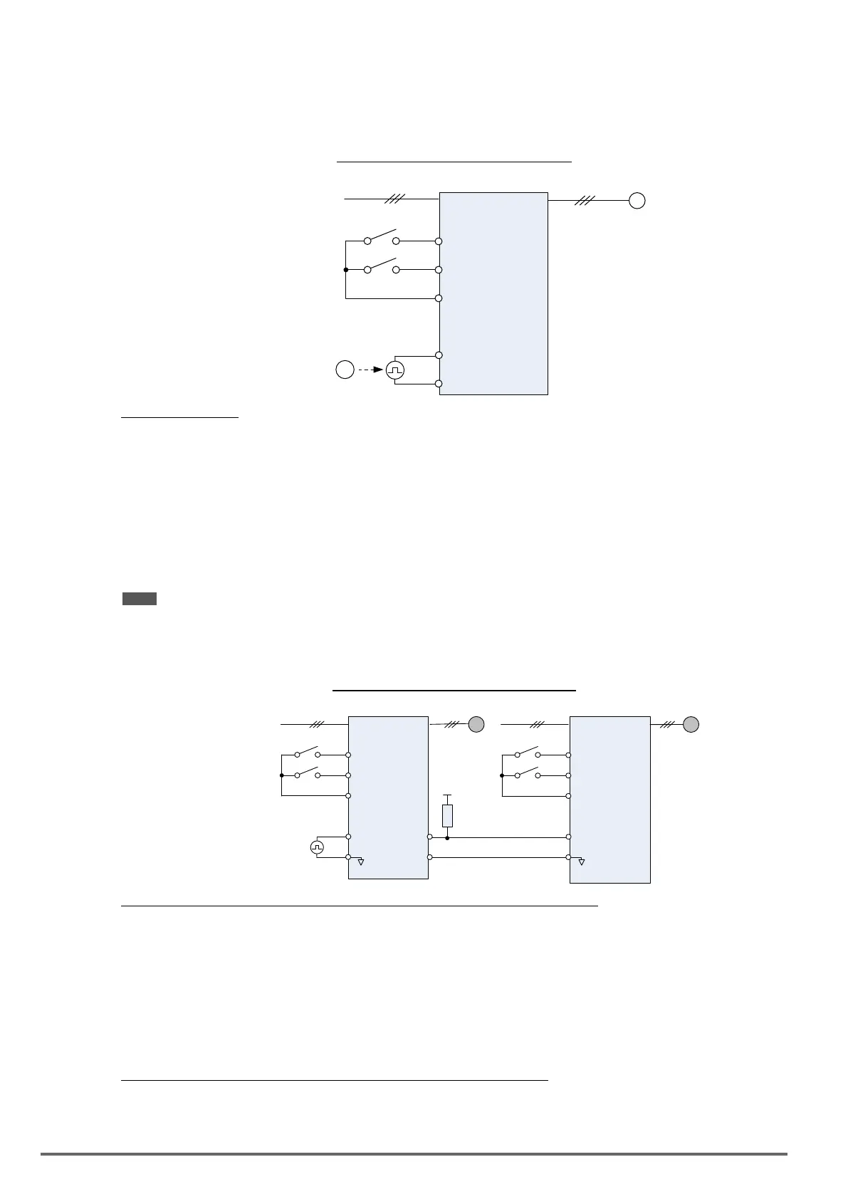
• ExampleA: Speed follower from external PG
Use the pulse input signal as frequency reference or synchronization operation. Refer to Fig. 4.4.31.
Figure4.4.31SpeedfollowerfromexternalPG
M
Inverter
S1
S2
24VG
PI
VSS
(*1 )
PG
Fwd Run/Stop
Rev Run/Stop
Parameter settings:
1. Frequency reference selection: 00-05=4 (Pulse input)
2. Pulse input’s function selection: 03-30=0 (General pulse input)
3. Pulse input scale: 03-31 (set the number of pulse in Hz to match maximum output frequency, 01-02)
4. Pulse input gain: 03-32 (Set the input gain of the pulse frequency set by 03-31)
5. Pulse input bias: 03-33 (Set the input bias of the pulse frequency set by 03-31)
6. Pulse input’s lter time: 03-34 (if the pulse input is unstable due to the interference, increase value.)
Use the forward and reverse multi-function inputs to choose motor direction.
Note: For higher accuracy use PG feedback in SV or V / f + PG control mode.
• ExampleB: Speed follower using two inverters
Figure4.4.32Speedfollowerusingtwoinverters
(INV2)
S1
M2
S2
24VG
PI
GND
FWD Run/Stop
REV Run/Stop
(INV1)
S1
M1
S2
24VG
PI
GND
FWD Run/Stop
REV Run/Stop
Master PG
etcs.
PO
GND
+5V
2.2K
Ω
Inverter #1 parameter settings: Frequency reference from PI signal (Master PG)
1. Frequency reference selection: 00-05=4 (Pulse input)
2. Pulse input’s function selection: 03-30=0 (General pulse input)
3. Pulse input scale: 03-31 (set the number of pulse in Hz to match maximum output frequency, 01-02)
4. Pulse input gain: 03-32 (Set the input gain of the pulse frequency set by 03-31)
5. Pulse input bias: 03-33 (Set the input bias of the pulse frequency set by 03-31)
6. Pulse input’s lter time: 03-34 (if the pulse input is unstable due to the interference, increase value.)
7. Pulse output function selection: 03-35=1 (Pulse output is output frequency
8. Scale pulse output parameter 03-36 to 100% of output frequency
Inverter #1 parameter settings: Frequency reference from analog signal
1. Frequency reference selection: 00-05=1 (Analog input)
2. Pulse output function selection: 03-35=
2 (Pulse output is output frequency)
3. Scale pulse output parameter 03-36 to 100% of output frequency
168 VDI100 • Instruction manual

 Loading...


