Inverter #2: parameter settings:
1. Frequency reference selection: 00-05=4 (Pulse input)
2. Pulse input’s function selection: 03-30=0 (General pulse input)
3. Pulse input scale: 03-31 (set the number of pulse in Hz to match maximum output frequency, 01-02)
4. Pulse input gain: 03-32 (Set the input gain of the pulse frequency set by 03-31)
5. Pulse input bias: 03-33 (Set the input bias of the pulse frequency set by 03-31)
6. Pulse input’s lter time: 03-34 (if the pulse input is unstable due to the interference, increase value.)
Note: When pulse output function is active, it is required to use the external pull-up resistor at the terminal of PO (the upper
limit current of PO is 50mA)
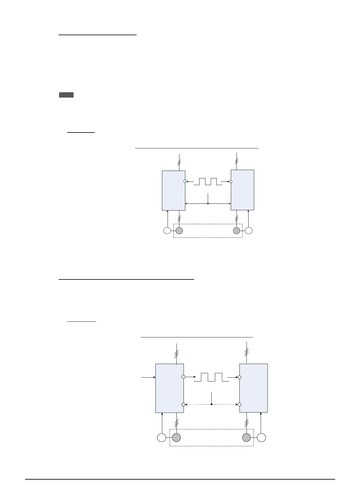
• Example C: Synchronized operation using pulse input
Figure4.4.33:Synchronizedoperationofusingpulseinput
IM
PG
(Slave)
PI
IM PG
A/B
A/B
SYNC
Pulse
Input
(Synchronized Operation)
(Slave)
PI
Connect pulse signal of an external pulse generator to the pulse input terminal PI of multiple follower inverters
for output speed synchronization.
Follow inverter #1 and Follower #2 parameter settings:
1. Frequency reference selection: 00-05=4 (Pulse input)
2. Pulse input’s function selection: 03-30=0 (General pulse input)
3. Set one of the Multi-function inputs Sn: 03-00 ~ 03-07=32 (Synchronization command)
• Example D: Synchronized operation of using pulse output master follower
Figure4.4.34Synchronizedoperationmasterfollower
IM
PG
(Master)
PI
IM PG
A/B
A/B
Frequency
Reference
SYNC
Pulse
Input
(Synchronized Operation)
(Follower)
PO
Sync
Sync
03-00 ~
03-07=32
03-00 ~
03-07=32
VDI100 • Instruction manual 169

 Loading...


