Figure4.4.35Analoginputsandrelatedparameters
+10V
AI 1
AI 2
GND
-10V
0 - 10V, -10V - +10V
0 - 10V / 0 - 20mA
4 - 20mA / 2 -10V
[
[
I
V
SW2
04-00 (Level Selection)
04-02 (Gain)
04-03 (Bias)
{
04-00 (Level Selection)
04-05 (Function Selection)
04-07 (Gain)
04-08 (Bias)
{
Related
Parameters
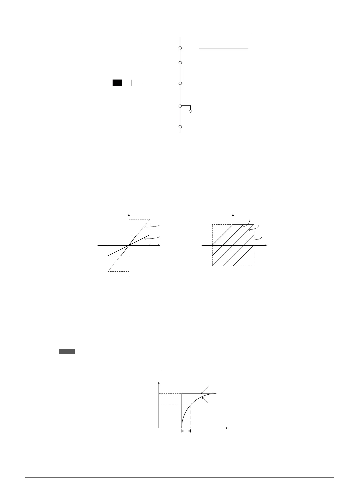
Gain setting: Sets the level in % that corresponds to a 10V, -10V or 20mA signal at the analog input.
(Set the maximum output frequency 01-02 to 100 %)
Bias setting: Sets the level in % that corresponds to a 0V or 4mA signal at the analog input.
(Set the maximum output frequency 01-02 to 100%)
Use both gain and bias setting to scale the input signal.
Figure4.4.36Gainandbiasoperations(forfrequencyreferencesignal)
Gain: 200%
Gain: 100%
200%
100%
10V
(20mA)
0V
(4mA)
-100%
-200%
-10V
Terminal
AI1,AI2
analog input
Frequency
Reference
+100%
-
100%
10V
(20mA)
-
10V
0V
(4mA)
Bias = positive
Bias = 0%
Bias = Negative
Terminal
AI1,AI2
analog input
(a)
Gain
(b)
Bias
Reference
(2) AI1 signal ltering time (04-01)
(3) AI2 signal ltering time (04-06)
All analog inputs (AI1, AI2) have a 1st order programmable input lter that can be adjusted when noise is pres-
ent on each of the incoming analog signal to prevent erratic drive control.
The lter time constant (range: 0.00 to 2.00 seconds) is dened as the time that the input step signal reaches
63% of its nal value.
Note: Increasing the filter time causes the drive operation to become more stable but less responsive to change to the
analog input.
Figure4.4.37Filtertimeconstant
Unfiltered
signal
Filtered
signal
Filter time constant (04-01)
63
100
%
t
(4) AI2 function setting (04-05)
AI2 is multi-function analog input terminal function selection. Refer to Table 4.4.11 for function overview.
VDI100 • Instruction manual 173

 Loading...


