-100.0~100.0%
04-16 AO2 function Setting
See parameter 04-11
04-17 AO2 gain
0.0~1000.0%
04-18 AO2 bias
-100.0~100.0%
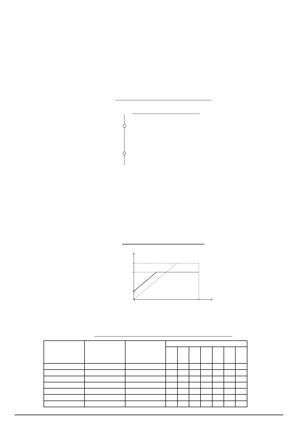
For the analog output and related parameters, refer to gure 4.4.50.
Figure4.4.50Analogoutputsandrelatedparameters
AO1
AO2
Related Parameters
04-11 (Function Selection)
04-12 (Gain)
04-13 (Bias)
{
04-16 (Function Selection)
04-17 (Gain)
04-18 (Bias)
{
AnalogoutputAO1andAO2adjustment(04-12,04-13and04-17,04-18)
Signal: Use parameter 04-11 to select the analog output signal for AO1 and parameter 04-16 to select the
analog output signal for AO2.
Gain: Use parameter 04-12 to adjust the gain for AO1 and parameter 04-17 to adjust the gain for AO2.
Adjust the gain so that the analog output (10V/20mA) matches 100% of the selected analog output signal (04-
11 for AO1 and 04-16 for AO2).
Bias: Use parameter 04-13 to adjust the bias for AO1 and parameter 04-18 to adjust the bias for AO2.
Adjust the bias so that the analog output (0V/4mA) matches 0% of the selected analog output signal (04-11 for
AO1 and 04-16 for AO2).
Figure4.4.51Analogoutputleveladjustment
Monitored items
100%
0%
Analog Output Signal
10V(or 20mA) × Gain
(20mA) 10V
(4mA) 0V
{
Bias
Analogoutputterminalfunctionselection(04-11and04-16)
Refer to the following table 4.4.12.
Table4.4.12Selectionofanalogoutputterminalsfunction(04-11and04-16)
04-11, 04-16
Parameter setting
Function
(Keypad display)
Monitoring
Parameters
Group 12
Control mode
V/f
V/f
+
PG
SLV SV
PM
SV
PM
SLV
SLV2
0 Output Freq 12-17 O O O O O O O
1 Freq Ref 12-16 O O O O O O O
2 Output Voltage 12-19 O O O O O O O
3 DC Voltage 12-20 O O O O O O O
4 Output Current 12-18 O O O O O O O
5 Output kW 12-21 O O O O O O O
6 Motor Speed 12-22 O O O O O O O
180 VDI100 • Instruction manual

 Loading...


