04-11, 04-16
Parameter setting
Function
(Keypad display)
Monitoring
Parameters
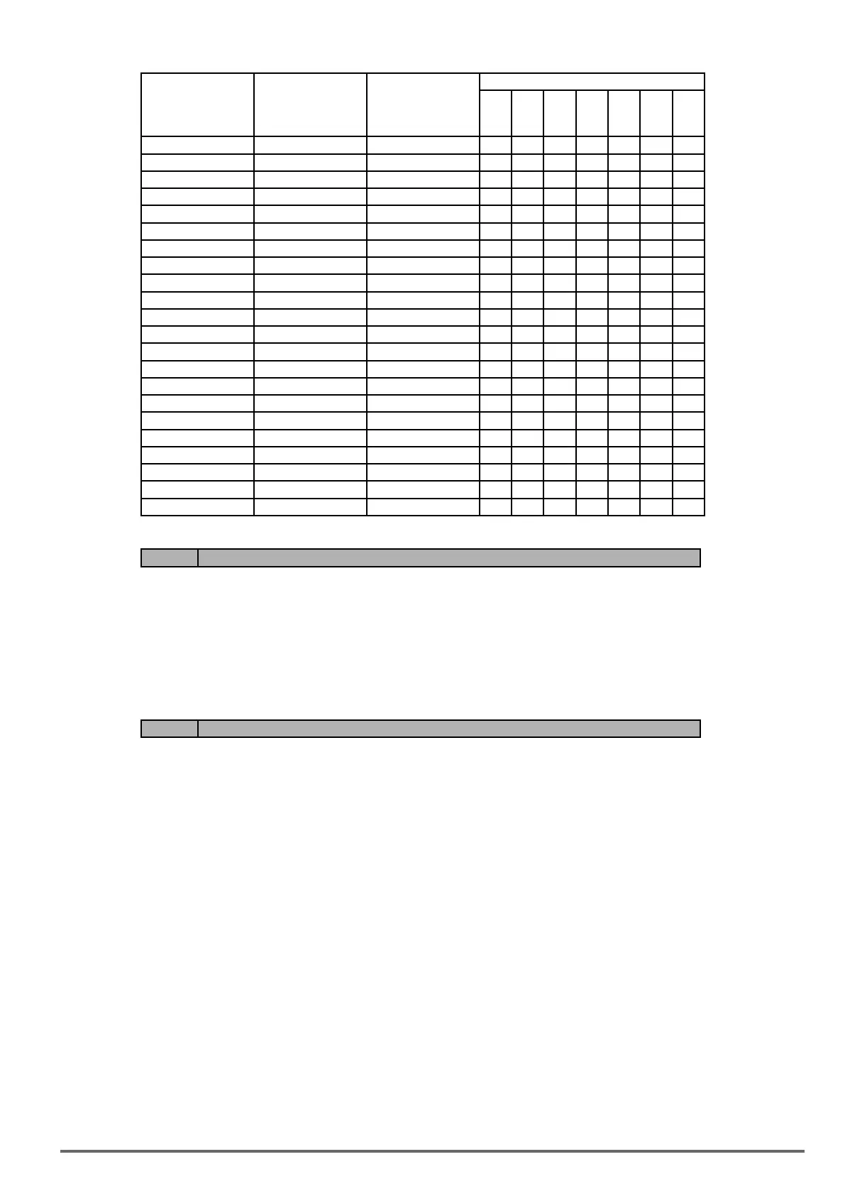
Group 12
Control mode
V/f
V/f
+
PG
SLV SV
PM
SV
PM
SLV
SLV2
7 Output PF 12-23 O O O O O O O
8 AI1 Input 12-25 O O O O O O O
9 AI2 Input 12-26 O O O O O O O
10 Torque Ref 12-27 X X O O O O X
11 Current Iq 12-28 X X O O O O X
12 Current Id 12-29 X X O O O O X
13 Speed Deviation 12-30 X X X O O X X
14 Reserved X X X X X X X
15 ASR Output 12-32 X O X O O X X
16 Reserved - X X X X X X X
17 Voltage Ref Vq - X X O O O O X
18 Voltage Ref Vd - X X O O O O X
19 Reserved - X X X X X X X
20 Reserved - X X X X X X X
21 PID Input 12-36 O O O O O O O
22 PID Output 12-37 O O O O O O O
23 PID Setpoint 12-38 O O O O O O O
24 PID Feedback 12-39 O O O O O O O
25 Output Freq (SFS) - O O O O O O O
26 PG Feedback 12-33 X O X O O X X
27 Reserved - X X X X X X X
28 Comm Control - O O O O O O O
Code Parameter Name / Range
04-19 AO2 Output Signal Type
(0): AO2 0~10V
(1): AO2 4~20mA
It is required to be with the setting of SW6 on the conrtol board when AO2 analog output signal type is active.
When 04-19=0 (AO2 is 0~10V) and SW6 on the control board is V, AO2 output signal type is voltage.
When 04-19=1 (AO2 is 4~20mA and SW6 on the control board is I, AO2 output signal type is current.
Code Parameter Name / Range
04-20 Filter Time of AO Signal Scan
(0.00~0.50) s
Setting of parameter 04-20 is used for ltering momentary change in analog output signal. When it is enabled,
system response will lower down and interference protection will enhance.
VDI100 • Instruction manual 181

 Loading...


