08-17=2: Low-torque detection is enabled during running.
Parameter 08-18 selects the way the inverter acts when an over-torque condition is detected.
08-18=0: When a low-torque condition is detected the inverter displays and low-torque detection fault and the
motor decelerates to a stop.
08-18=1: When a low-torque condition is detected the inverter displays a low-torque detection alarm and con-
tinues to run.
08-18=2: When a low-torque condition is detected the inverter displays and low-torque detection fault and the
motor coasts to a stop.
• Setting Example of less torque detection:
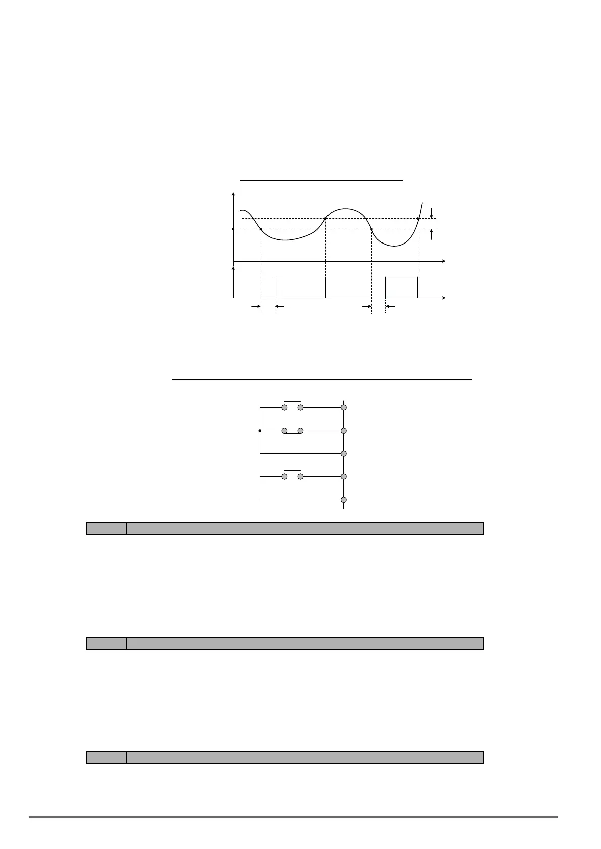
Figure4.4.74Lowtorquedetectionoperation
Inverter output current
( or motor output torque )
DetectIon Level (08-19)
Undertorque
detection
signal
t
t
08-20
08-20
10% hystersis
width
Over and low torque detection condition can be output to the multi-function digital outputs (R1A-R1C, R2A-
R2C) by setting parameters 03-11 to 03-12 to 12 or 25. Refer to gure 4.4.75 for more information.
Figure4.4.75Over-torque/lowtorquedetectionmulti-functiondigitaloutputterminal
R1A
R1B
R1C
R2A
R2C
}
}
03-11
03-12
Code Parameter Name / Range
08-23 Ground Fault (GF) selection
0: Disable
1: Enable
08-23=1: If the inverter leakage current is greater than 50% of inverter rated current and the ground fault func-
tion is enabled (08-23), the keypad will display a “GF Ground Fault” (GF), motor will coast to a stop and fault
contact is activated.
Code Parameter Name / Range
08-24 External Fault Operation Selection
0: Deceleration to stop
1: Coast to stop
2: Continue operation
Select operation selection when an external fault occurs. Refer to the multi-function inputs on how to set up the
inverter for an external fault input.
Code Parameter Name / Range
08-25 Detection selection of external fault
0: Immediately detect when the power is supplied
1: Start to detect during operation
208 VDI100 • Instruction manual

 Loading...


