Overvoltage suppression is used for the application of likely causing to energy recharge.
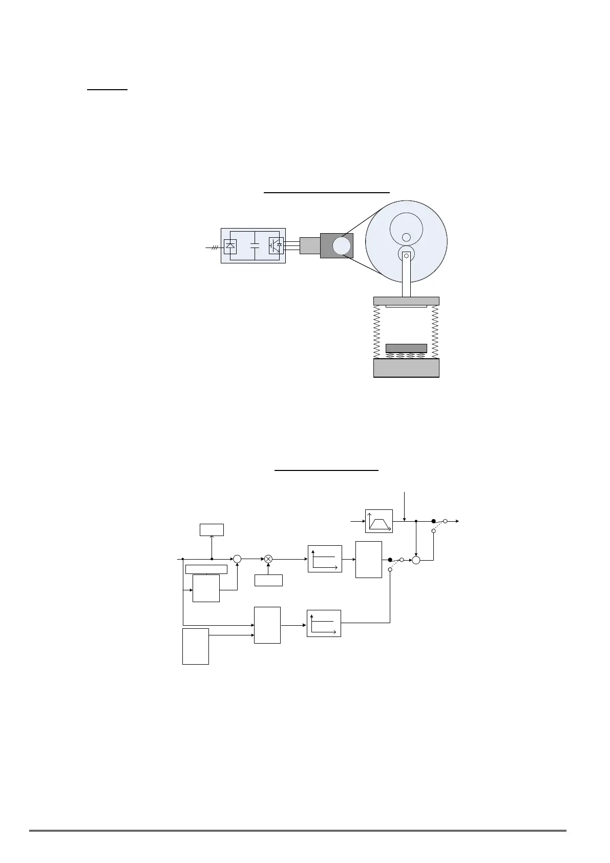
Example: there are two situations causing excessive energy to recharge the inverter in stamping application
(1) When cam clutch is not engaged, the motor will accelerate and start ywheel. When motor decelerates,
the rotation speed will higher than motor speed owing to the large ywheel’s inertia and then recharge the
inverter.
(2) When cam clutch is engaged, the motor will start ywheel and compress the spring. When the highest point
of the cam moves beyond its center, the spring will release the power to the ywheel and excessive energy
output recharge the inverter.
Figure4.4.90StampingOperation
cam
clutch
FLYWHEEL
Motor
Inverter
f
out
f
motor
Gear
box
Motoring : f
out
> f
motor
Overhauling : f
out
< f
motor
Over-voltage prevention (OVP) function monitors the DC-bus voltage and adjusts the speed reference, acceler-
ation and deceleration rate, to prevent the inverter from tripping on an overvoltage.
When the speed reference is reduced, the motor will start to decelerate. When the inverter is operating at a
xed output frequency and excessive regenerative energy back to the inverter is detected the inverter will ac-
celerate the motor in order to reduce the DC-bus voltage. Refer to gure 4.4.91.
Figure4.4.91OVPoperation
11-33
11-34
11-35
DC bus
voltage
DC bus filter
12-20
DC bus
voltage
+
-
11-36
Gain
Frequency
Reference
Limit
OVP
accel /
decel
time
11-37
Frequency
Reference
Fout
SFS
+
+
11-40= 0
11-40 = 1 or 2
Output
Frequency
After SFS
OVP 2
accel /
decel
time
11-37
11-40 = 1
11-40 = 2
11-28
OVP2
Gain
When 11-40=1: OV prevention Mode 1
1) DC voltage lter is used to provide a stable reference value for determining the change in DC voltage
change during regenerative operation.
- Adjust the DC voltage ltering increase rate parameter 11-33 (DC Voltage Filter Rise Amount). When the
DC voltage exceeds 11-33 +11-35 (DC Voltage Filter Deadband Level), the output of the lter will increase.
- Adjust the DC voltage ltering decrease rate parameter 11-34 (DC Voltage Filter Fall Amount). When the
DC voltage exceeds 11-33 +11-35 (DC Voltage Filter Deadband Level), the output of the lter will decrease.
- Monitor the DC voltage lter output by 12-20 (DC voltage lter value).
- Set the DC voltage lter decrease rate (11-34) to a greater value than the value of the DC voltage ltering
increase rate (11-33).
230 VDI100 • Instruction manual

 Loading...


