2) When the inverter is operation at a xed output frequency, the OVP function will monitor the DC-bus voltage
to detect regenerative operation.
In case of a regenerative condition the inverter calculates the delta DC bus voltage value and multiplies the
value with parameter 11-36, the result is added to the frequency reference accelerating the motor to prevent on
an overvoltage condition.
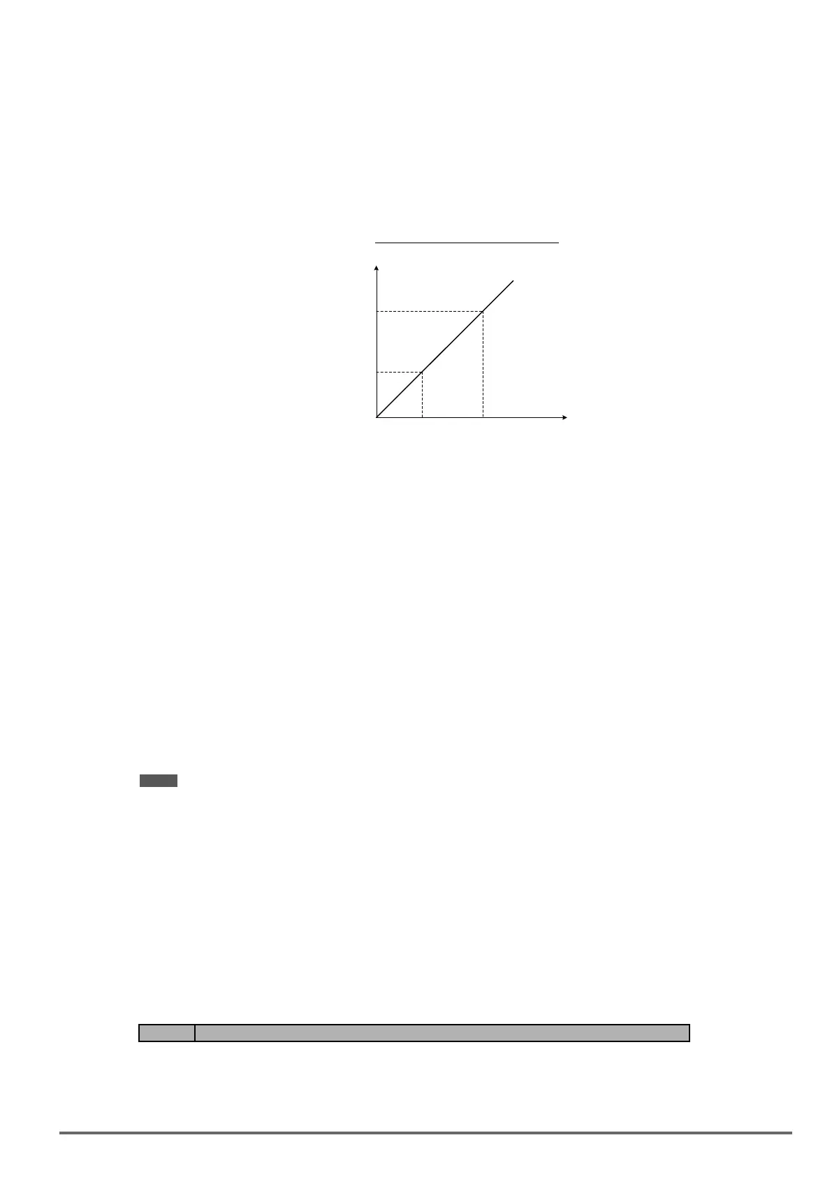
When the regenerative energy decreases, the inverter output frequency will return to the actual frequency refer-
ence. Deceleration rate is based on the DC voltage, as shown in Figure 4.4.92.
Figure4.4.92OVPdecelerationtime
Deceleration
Time
00-24
(Tdec 4)
00-22
(Tdec 3)
700V
750V
OVP
Deceleration
Start (11-38)
OVP
Deceleration
Stop (11-39)
DC bus
voltage
3) When the inverter is stopped, the deceleration rate can be set with parameter 00-15 (Tdec1). In case the
DC voltage is too high, the inverter will decelerate based on the OVP deceleration time as shown in Figure
4.4.92.
- Set DC-bus voltage in parameter 11-38 (start voltage of OVP deceleration) and set OVP deceleration rate in
00-22 (Tdec3).
- When the DC voltage reaches this level, it is necessary to decelerate rapidly in order to prevent the delta
DC voltage of becoming too large.
- When DC voltage reaches the setting of 11-39 (stop voltage of OVP deceleration), it will decelerate based
on the set value of 00-24 (Tdec4)
- Deceleration rate is linear based on the slope dened by the start point (11-38) and end point (11-39).
4). Enable the OVP function with parameter 11-40 set to 1 or 2. The following parameter default values will be
changed when the OVP function is enabled:
07-12=1 (Stop mode: coast to stop)
00-14 (Tacc1)= 5.0 s (the frequency reference acceleration rate when DC voltage is too high.)
00-22 (Tdec3)= 20.0 s (low setting point of OVP deceleration rate).
00-24 (Tdec4)= 100.0 s (high setting point of OVP deceleration rate).
Note: S curve should be disabled when using the OVP function (11-04~11-07=0.0sec).
When 11-40=2: OV prevention Mode 2
The process of OV prevention mode 2 is the same as that of OV prevention mode 1 but it strengthens more
the part of DC BUS over the deceleration stop voltage of OV prevention (11-39) in Fig.4.4.92. It can accelerate
frequency compensation to avoid OV protection by increasing frequency gain of OV prevention 2 (11-28).
When 11-40=3: OV prevention Mode 3
T=The inverter raise the output frequency temporarily to avoid OV, the output frequency wont higher than the
value of 01-02 (Maximum Output Frequency of Motor 1).Please adjust the value of 01-02 according to applica-
tion.
If it still occur OV in 11-40=3, please raise the value of 11-64 in 0.1 unit.
Code Parameter Name / Range
11-64 Acceleration Speed Gain Adjustment
0.1~10.0
It will inuence the speed and current if the value of 11-64 is too high.
VDI100 • Instruction manual 231

 Loading...


