Code Parameter Name / Range
11-65 Target Main Circuit Voltage
230V: 200V~400V
400V: 400V~800V
11-41 Reference frequency loss detection
0: when reference frequency disappears, the deceleration will stop.
1: when reference frequency disappears, continue to operate according to the proportion of reference frequency x 11-42.
11-42 Reference frequency loss level
0.0~100.0 %
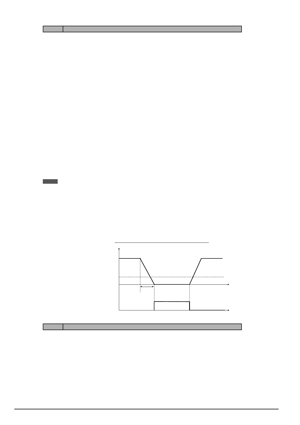
A Reference frequency loss is detected when the frequency command falls 90% within 360ms.
The action performed when a reference loss is detected is set with parameter 11-41.
11-41=0: Inverter will decelerate to a stop when a reference loss is detected.
11-41=1: Inverter will continue to operate; reference frequency is the value of Maximum Output Frequency of
Motor 1 x the level set in parameter 11-42.
The inverter will return to normal operation when:
(1) The reference frequency is restored while running and the reference level exceeds 80% of the master fre-
quency command.
(2) Stop command is issued.
Notes:
- Reference frequency loss level (11-42) is corresponding to the maximum output frequency of Motor 1 (01-
02).
- Reference frequency loss level is used in the analog signal (1: AI1 or 7: AI2) from the selection of main
frequency source (00-05).
Refer to the following Fig. 4.4.93 for the operation diagram of multi-function digital output (03-11~03-12) when
the analog frequency command is in the loss of frequency command.
Figure4.4.93Operationinreferencefrequencyloss
t
100%
360ms
Analog Frequency
Command
Analog frequency
command lossing
digit output
03-11=26 or 03-12=26
t
10%
OFF
OFF
ON
Code Parameter Name / Range
11-43 Hold frequency at start
0.0~599.0 Hz
11-44 Frequency hold time at start
0.0~10.0 s
11-45 Hold frequency at stop
0.0~599.0 Hz
11-46 Frequency hold time at stop
0.0~10.0 s
232 VDI100 • Instruction manual

 Loading...


