Refer to parameter 20-28 to set PG motor direction.
A position is dened by the number of rotations plus the number of pulses.
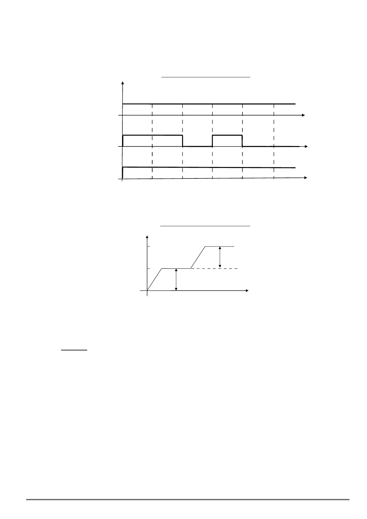
When multi-position function is used, position command enable (Multi Pos. Enable, DI is set to 52) is required
to be ON so the inverter can receive the external position command. Refer to Fig. 4.4.131.
Figure4.4.131PositionEnableDiagram
t
t
Position
Command
Enable
Position 0 Position 1
Position 2
Position 3
Position 4
Position
Command
of Inverter
Position 5
External
Position
Position 0
Position 1
Position 1
Position 3 Position 3
Position 3
Multi-position mode is the absolute type. If the rst section is at 100 pulse and make the motor rotate at more
than 100 pulse, then the second section is required to set at 200 pulse. Refer to Fig. 4.4.132.
Figure4.4.132theabsolutetypediagram
Time (t)
Position setting (21-10~21-41):
Motor Position Setting of N section = Rotation Cycles Command of N section x PG Pulse (20-27) + Pulse Command of N section
Example: 2 Positions
Motor encoder is 1024 PPR.
Position 1: Rotate motor shaft in forward direction 180 degrees, set rotation cycle to 0 and pulse number to 512
(1/2 x 1024). Positive number indicated forward direction.
Position 2: Rotate motor shaft 1reverse 270 degrees (-768 pulses), set rotation cycle to 0 and pulse number to
-768 (- 3/4 x 1024). Negative number indicated forward direction.
VDI100 • Instruction manual 279

 Loading...


