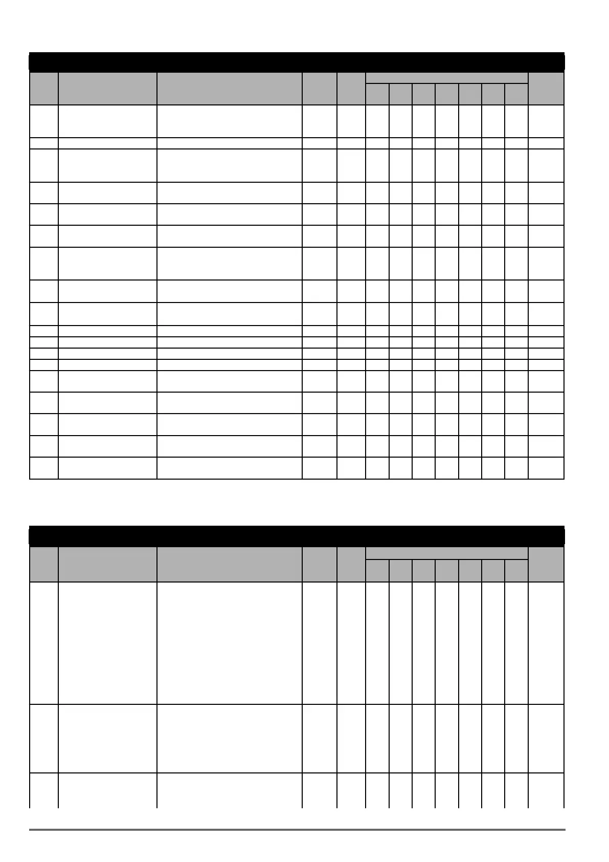
Group 11: Auxiliary Parameters
Code Parameter Name Setting Range Default Unit
Control mode
Attribute
V/f
V/f
+PG
SLV SV
PM
SV
PM
SLV
SLV2
1: When Operator’s UP/DOWN is Enabled,
it will be Enabled after Frequency Modi-
fication.
11-57 Reserved
11-58
Record Reference Fre-
quency
0: Disable 0 - O O O O O O O *1
1: Enable
11-59
Gain of Preventing Oscil-
lation
0.
00~2.50 * O O X X X X O
11-60
Upper Limit of Preventing
Oscillation
0~100 * % O O X X X X O
11-61
Time Parameter of Preven-
ting Oscillation
0~100 0 O O X X X X O
11-62 Selection of Preventing
Oscillation
0: Mode1 1 O O X X X X O
1: Mode2
2: Mode3
11-63 Strong Magnetic Selection 0: Disable 1 X X O O X X X
1: Enable
11-64
Acceleration Speed Gain
Adjustment
0.1~10.0 1.0 - O X X X X X O
11-65 Target Main Circuit Voltage
230V: 200V~400V 370 - O X X X X X O
11-66 Reserved
11-67 Reserved
11-68 Reserved
11-69
Gain of Preventing Oscil-
lation 3
0.00~200.00 5.00 % O O X X X X X
11-70
Upper Limit of Preventing
Oscillation 3
0.01~100.00 5.00 % O O X X X X X
11-71
Time Parameter of Prevent-
ing Oscillation 3
0~30000 100 ms O O X X X X X
11-72
Gain of Preventing Oscilla-
tion for switch frequency 1
0.01~300.00 30.00 Hz O O X X X X X
11-73
Gain of Preventing Oscilla-
tion for switch frequency 2
0.01~300.00 50.00 Hz O O X X X X X
*: Refer to the attachment 1.
** If the maximum output frequency of motor is over 300HZ,the frequency resolution is changed to 0.1Hz
Group 12: Monitoring Parameters
Code Parameter Name Setting Range Default Unit
Control mode
Attribute
V/f
V/f
+PG
SLV SV
PM
SV
PM
SLV
SLV2
12-00
Extended Display Mode
(LED)
00000 ~77777.
Each digit can be set to 0 to 7 as listed:
00000 - O O O O O O O
*1
*6
0: Default display (frequency¶meters)
1: Output Current
2: Output Voltage
3: DC voltage
4: Temperature
5: PID feedback
6: Analog Signal Input. (AVI)
7: Analog Signal Input. (ACI)
12-01
PID Feedback Display Mode
(LED)
0: Display the Feedback Value by Integer
(xxx)
0 O O O O O O O *6
1: Display the Feedback Value by the
Value with One Decimal Place (xx.x)
2: Display the Feedback Value by the
Value with Two Decimal Places (x.xx)
12-02
PID Feedback Display Unit
Setting (LED)
0: xxxxx (no unit) 0 O O O O O O O *6
1: xxxPb (pressure)
78 VDI100 • Instruction manual

 Loading...


