- 135 -
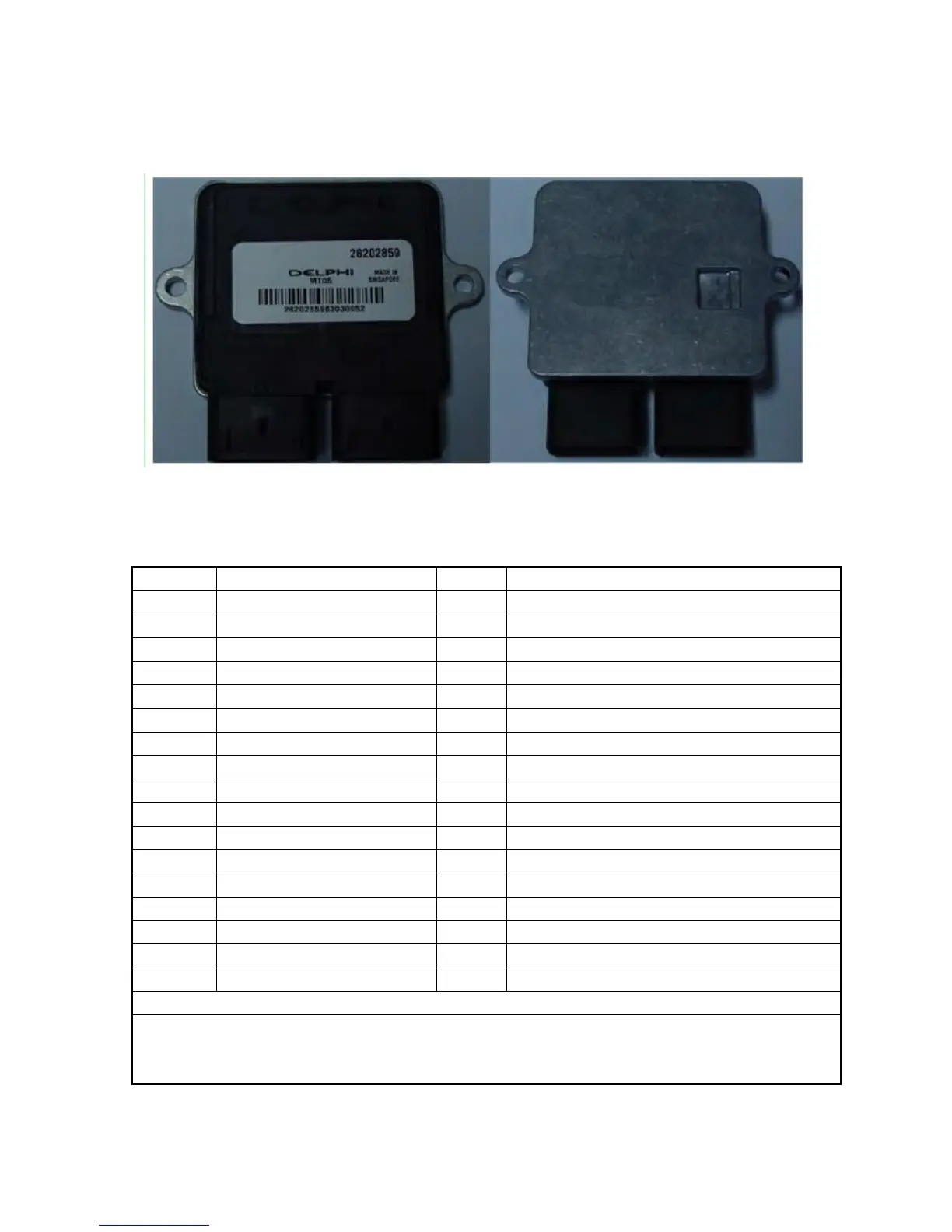
16.2.1.2 Appearance of ECU:
16.2.1.3 The ECU pin definitions:
J1-1 Stepper engine A high pin J2-1 Ignition coil driver pin
J1-2 J2-2 System ground pin
J1-3 J2-3 K-wire communication pin
J1-4 J2-4 High potential pin of the crankshaft signal
J1-5 J2-5 Injector drive pin
J1-6 Rotating speed signal pin J2-6
J1-7 CAN line signal low pin J2-7 Oxygen sensor heating pin
J1-8 CAN line signal high pin J2-8 Intake air temperature sensor signal pin
J1-9 System ground pin J2-9
J1-10 J2-10 System 5V reference voltage ground pin
J1-11 Stepper Engine A low pin J2-11 Intake air pressure sensor signal pin
J1-12 Stepper engine B high pin J2-12 Throttle body position sensor signal pin
J1-13 Stepper engine B low pin J2-13 Low potential pin of the crankshaft signal
J1-14 Dump switch (low effectiveness) J2-14 Water temperature sensor signal pin
J1-15 Speed signal pin J2-15 Ignition power (12V positive voltage after the key)
J1-16 Spara discrete input J2-16 5V reference voltage
J1-17 Oil pump control signal pin J2-17 Oxygen sensor signal pin
J1-18 Neutral switch pin J2-18 Battery power (battery 12V positive power supply)
Note:
J1 means the gray plug in the ECU while J2 means the black plug in the ECU; J1-1 means the 1st pin in
ECU gray plug.