- 81 -
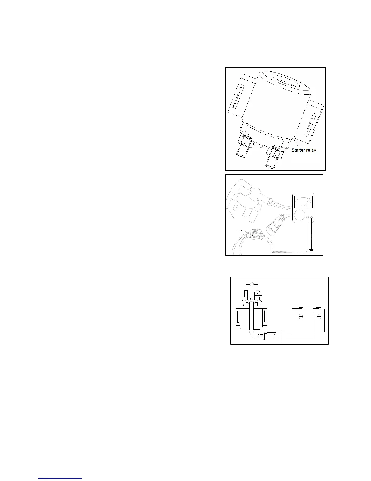
7.4 Starting Relay
7.4.1 Actuation Inspection
Take down the protecting plate of vehicle block.
When the ignition switch is set at “ON” position, press starting
motor and a “Click” sound can be heard.
“Click” sound indicates normal.
No sound: • Check starting relay voltage.
• Check starting relay ground wire loop.
• Inspect starting relay actuation.
7.4.2 Starting relay voltage inspection
Lift and support the main stand. Measure the voltage between
negative pole (green/yellow) of starting relay connector and vehicle
ground wire.
Set ignition switch at “ON” position and catch the brake lever.
Battery voltage shall meet the specified.
When there is no voltage at wire terminal of starting relay, inspect
braking switch continuity and lead wire.
7.4.3 Starting relay ground loop inspection
Remove starting relay connector.
Inspect continuity between grey wire of connector terminal and
vehicle ground wire.
When the starting button is pressed, continuity between grey wire of
connector and vehicle ground wire shall be fine.
If there is no continuity, inspect starting button continuity and lead
wire.
7.4.4 Actuation Inspection
Connect starting relay with battery and connect terminal of starting motor with multimeter.
Connect fully charged battery between black wire and green/yellow wire of relay. A “tap” sound of operation
can be heard on the relay and resistance displayed by multimeter is zero.
Ω
Ω
灰
Grey