- 66 -
Set multimeter to position of AC voltage
Limited voltage: 13.1 (+/-) 0.5V/5.000rpm
If limited voltage is beyond the specified range, check voltage-cuttent regulator.
5.5 Voltage-current Regulator
1.5.1 Loop inspection on main wiring terminals
Disconnect the 6P plug on the voltage-current regulator.
Check continuity between main wiring terminals in the following way:
Item (wire color)
Judgment
Battery (red) and
ground of vehicle
block
It is battery voltage.
Ground wire (black)
and ground of vehicle
block
There is a lead wire.
Charging coil (white)
and ground of vehicle
block
No power flowing between
magneto coil and ground
Between charging
coils (while 1 and
white 2)
There is resistance between
coils
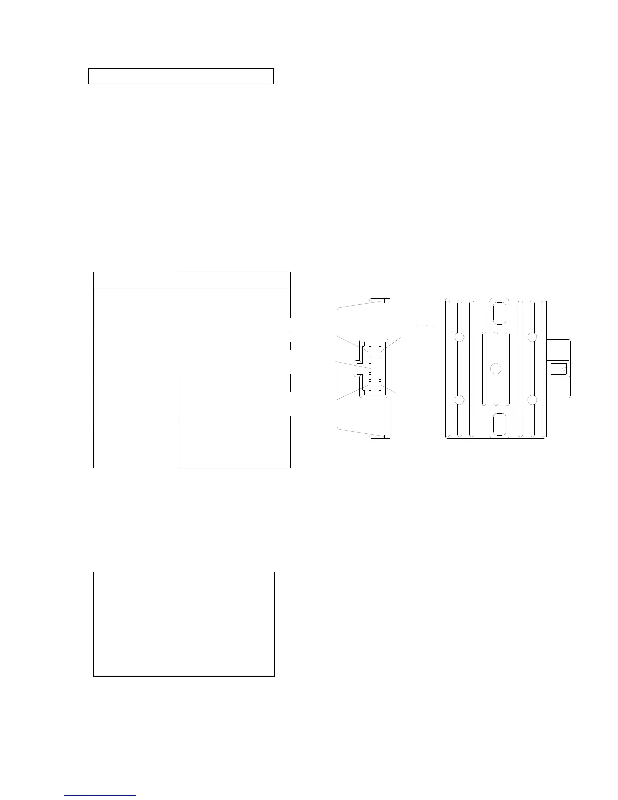
5.5.2 Voltage-current regulator inspection
When main wiring terminal is normal, check if plug of voltage-current regulator is of poor contact and
measure impedance value between terminals of voltage-current regulator itself.
* Attention
• Do not touch the metal part of
multimeter probe with your finger.
• Check with a multimeter. If impedance
values measured by different multimeters
are not the same, it perhaps the inspection
is not correct.
When impedance value between terminals is abnormal, replace voltage regulator.
输出+
接红线
检测
接红/白
输出-
接黑线
交流输入
接白线
交流输入
接白线
Outpu