- 75 -
vehicle and remove connector of alternator. Trigger (blue/white) is connected with a shunt.
• When the measured voltage at CDI assembly terminal is abnormal, but measured voltage at alternator
terminal is normal, it indicates that the connector is of poor contact or wiring is broken.
• When measured results at both sides are abnormal, the trigger is damaged. Please refer to items listed in
Diagnosis Table and check.
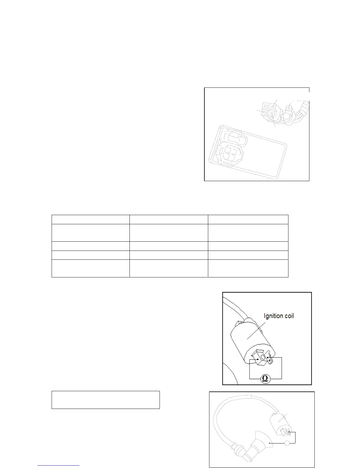
6.4 CDI Assembly
6.4.1 System Inspection
System inspection
Remove CDI assembly and check components related to the
ignition system at wiring terminal.
6.4.2 Inspection
Remove CDI assembly and check if connectors are loose or corrosive.
Item Measuring terminal Standard Value(20)
Main switch Red—Red/White On continuity when main
switch is “OFF”.
Trigger Red - Machine short cut 100-200Ω
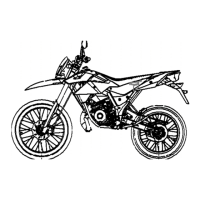
Primary coil of ignition coil Black/White—Black 0.4Ω (+/-) 10%
Secondary coil of ignition coil Black—spark plug cap (not
including spark plug)
4.5-5.5KΩ (+/-) 10%
6.5 Ignition Coil
6.5.1 Removal
Remove vehicle block cover.
Remove spark plug cap.
Remove primary lead wire of ignition coil.
Remove locknut of ignition coil and take out the ignition coil.
Install it in the reverse order of removal.
*Attention
The primary coil is installed with
black/white wire connector.
点火线图
Ω
Ignition coil
红/黑
蓝/白
黑
黑/白
Red/Blac