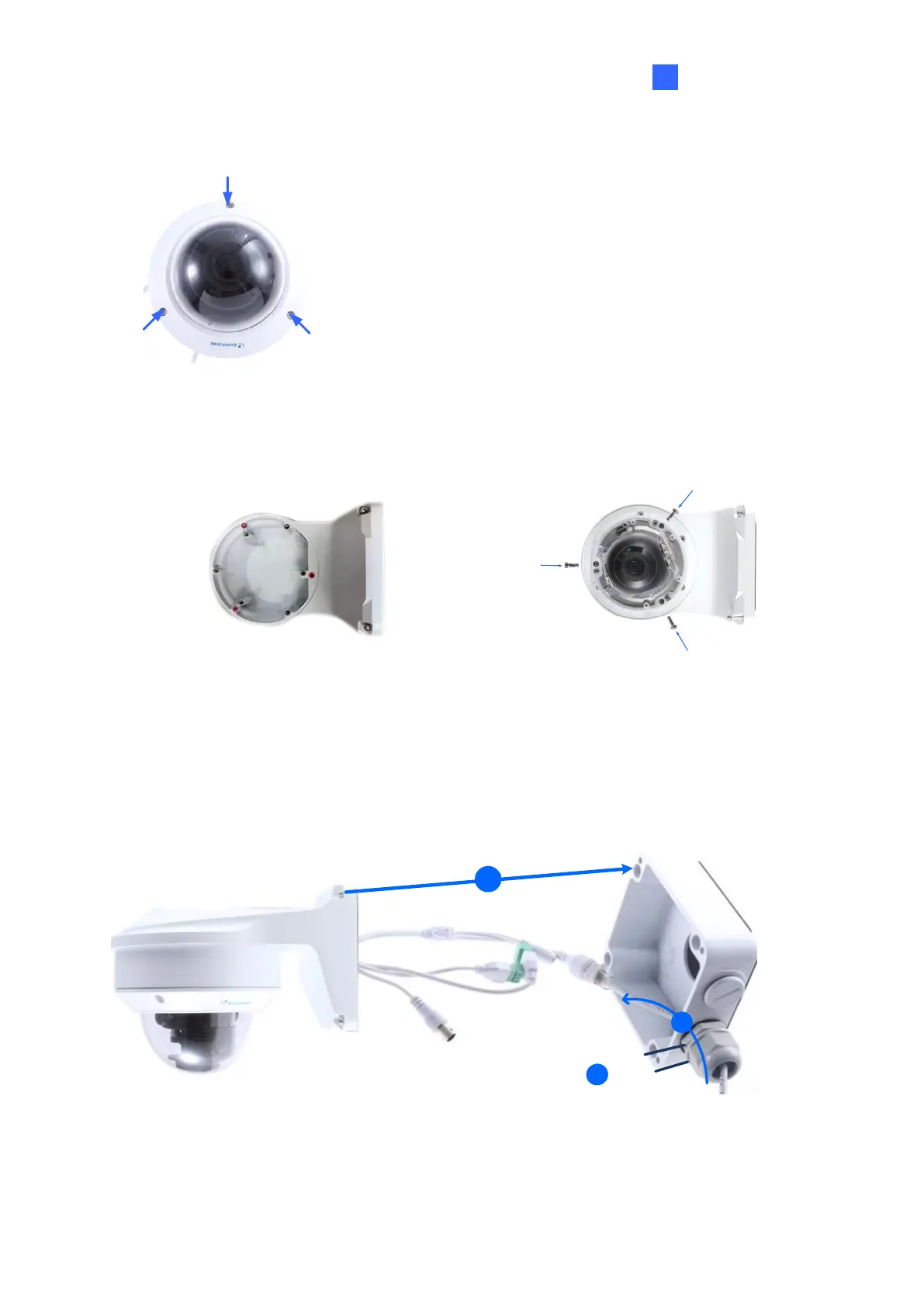
2. Unscrew the transparent dome cover with the supplied torx wrench.
Figure 1-92
3. Optionally insert a SD card into the slot.
4. Thread the camera cables through the bracket.
5. Secure the camera to the wall mount bracket with the provided short screws.
Figure 1-93
6. Thread the Ethernet cable through the PG21 conduit connector and the power box, as
shown in No 6, Figure 1-90. Then connect the cable to the camera.
7. Rotate the plastic ring to secure the conduit connector to the power box. Screw in the cap
shown in No 7, Figure 1-90.
8. Screw the wall mount bracket to the power box, as shown in No. 8, Figure 1-94.
 Loading...