Installation Instructions
4–16 INS 61301607027 Rev A US
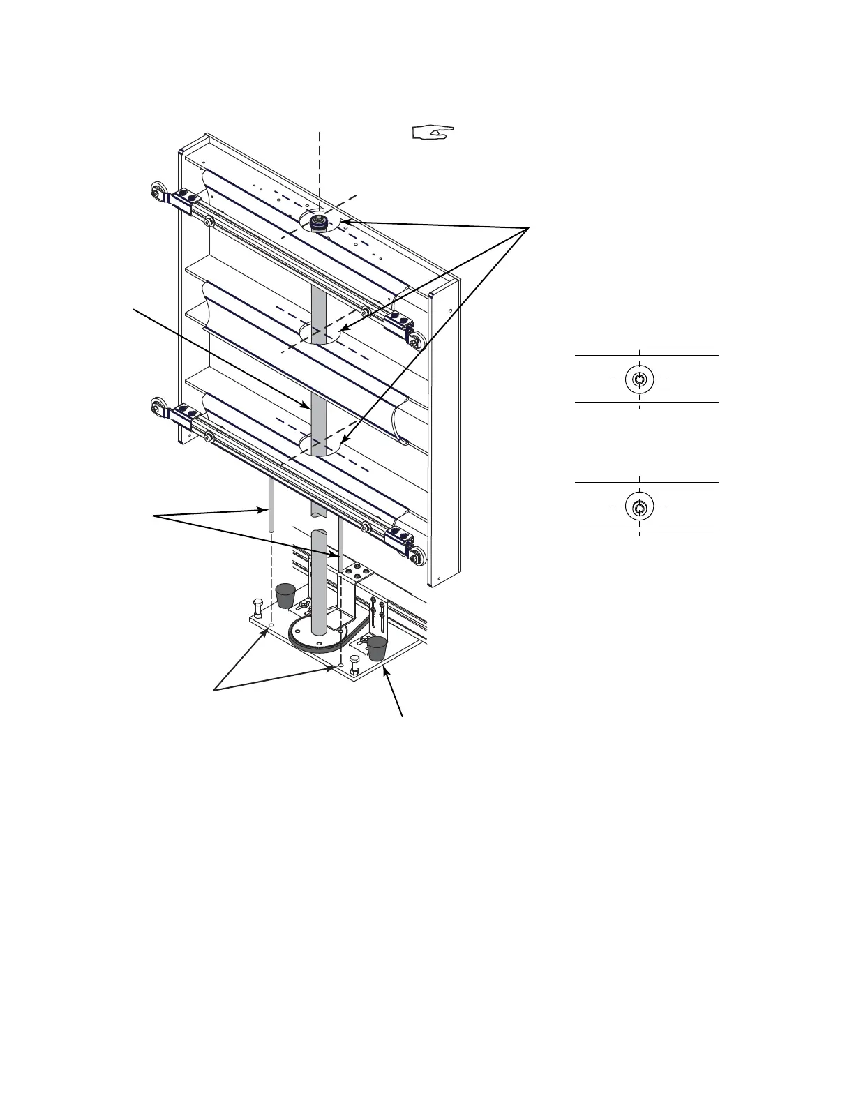
FIGURE 4–16. LIFT SCREW ALIGNMENT
10. Refer to Figure 4–16. Check that the alignment pins are centered over
the holes in the mounting plate.
11. Remove the plug from the top of the door cover and check that the lift
screw is vertically centered in the openings in the door plate.
12. Readjust the mounting plate as required and check for levelness from
side to side and back to back.
13. Remove the alignment pins and store them on the sides of the holder
for the spanner wrench.
14. Reinstall the rubber door bumpers.
Lift Screw
A07027-BG
Door cover removed for clarity.
Alignment
Holes
Alignment
Pins
Door Motor
Mounting Plate
Lift screw must be centered
in the openings in the door plate
Aligned Correctly
Not Aligned
TOP VIEW
(as viewed through opening in door cover)