Optional Equipment
5–2 INS 61301607027 Rev A US
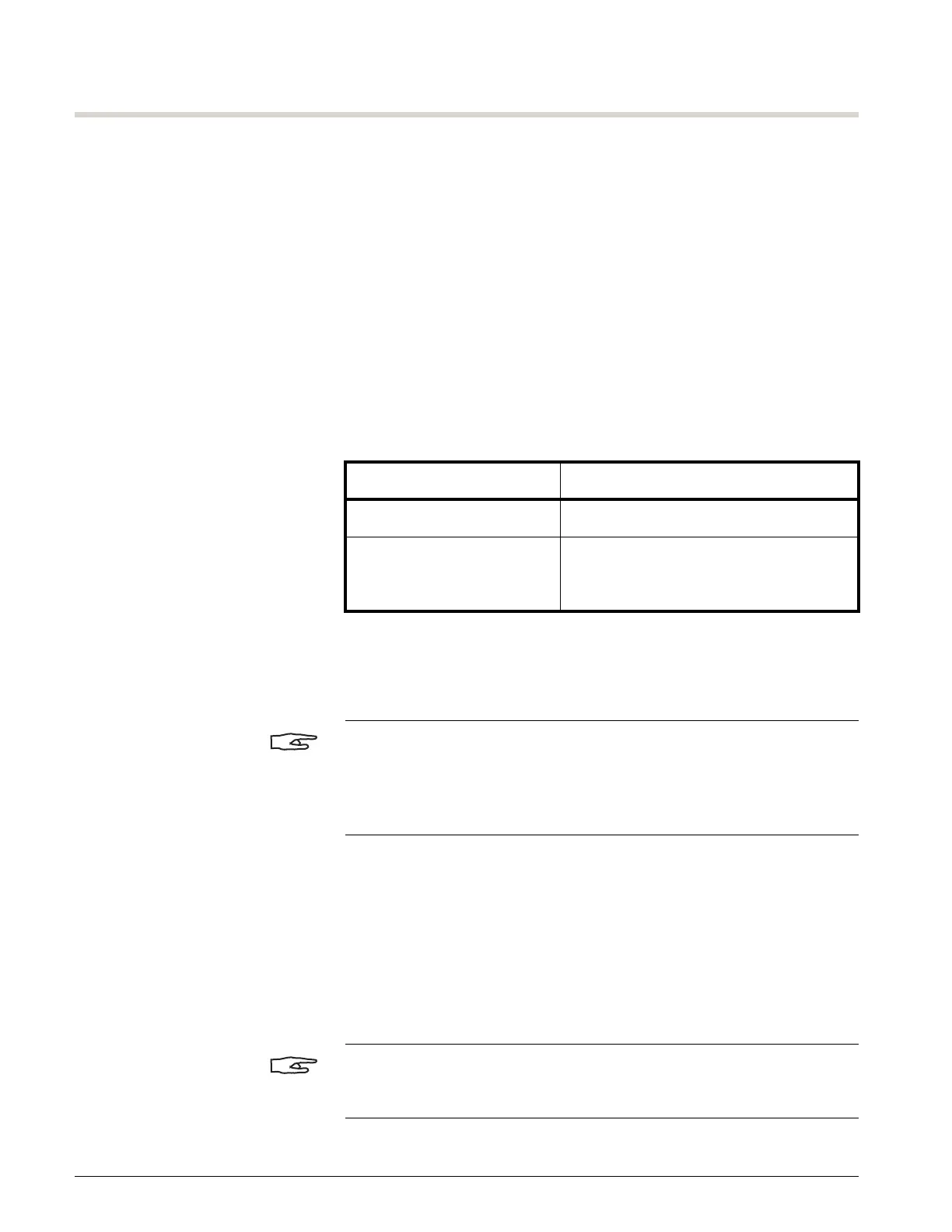
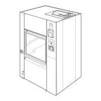
STEAM BOILER
SPECIFICATIONS The following utility connections are required for sterilizers with an integral
steam boiler:
• Manual shutoff valve, strainer, and pressure gauge in the hot water
supply line.
• Separate three-phase electrical service for the heating circuit.
For detailed specifications on electrical requirements, hot water (pressure,
flow, and quality), and connection sizes, refer to the roughing-in drawing
(Figure 6–1, Sheet 5 on page 6–6).
BOILER MODELS The steam boiler used varies based on the chamber length of the sterilizer.
Refer to the following table for the proper boiler unit.
CONNECTING THE PLUMBING The steam boiler is shipped mounted to the sterilizer with the steam output
and drain line connected to the sterilizer. The hot water supply and pressure
relief valve vent are supplied by the customer.
NOTE
Use unions on the hot water supply and pressure relief valve connections.
Recommendation: Pipe the pressure relief valve to a vented manifold
outside the equipment service area per ASME code.
To connect the plumbing to the boiler (see Figure 5–1):
1. Connect the hot water (HW) supply to the water strainer on the boiler.
2. Connect the outlet of the pressure relief valve (SV3) to a vent system.
3. If the boiler is a CAS-45A, connect the blow-down discharge line to a
separator tank (provided by customer).
NOTE
The ES-18/24/30/36/48 Blow-Down Separation Tank (Getinge PN 530957)
is suitable for this application.
TABLE 5–1. AVAILABLE STEAM BOILERS
CHAMBER LENGTH STEAM BOILER
26 in. GTS-30A
39 in. CAS-45A
51 in.