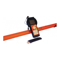
Probe CMD–Explorer
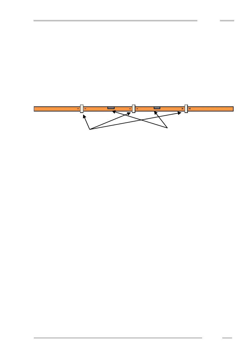
Put all four parts of the probe to each other having “T” and “I” marks in one
line. Transmitter, which is labeled by “I”, is to be connected on the left side.
Receiver, which is labeled by “T”, is to be connected on the right side. Two parts
with the 5-pin connector (connection to the control unit) and buttons are in the
middle. Then connect the connector and assemble the arms by turning the bayonet
rings. See picture below.
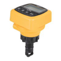
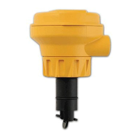
If you wish to measure with maximum depth range (HIGH), turn the probe
to position with the black strip and “Hi” label on the upper side. If you wish to
measure with half depth range (LOW), turn the probe to position with the black
strip and “Lo” label on the upper side.