58452 VXIbus Universal Power Meter
4-2 Publication 21555, Rev. E, September 2002
4.3 Calibration Procedures
Perform the Calibrator Output Power Reference Level check. If the unit fails to meet the power output
specification within 0.981mW (minimum) to 1.019mW (maximum) limits, then proceed with the
following steps:
4.3.1 Calibrator Output Power Reference Level
The Calibrator Output power reference is factory adjusted to 1mW±0.7%. To achieve this accuracy,
Giga-tronics uses a precision measurement system with accuracy to
±0.5% (traceable to the NIST) and
allows for a transfer error of
±0.2% for a total of±0.7%. If an equivalent measurement system is used for
verification, the power reference oscillator output can be verified to 1mW
±1.9% (±1.2% accuracy
+
±0.5% verification system error +±0.2% transfer error =±1.9% maximum error).
This test procedure is valid for an ambient temperature range between +15 °C and +35 °C (+59 °F to
+95 °F).
To ensure maximum accuracy in verifying the Calibrator Output power reference, the following
procedure provides step-by-step instructions for using specified test instruments of known capability. If
equivalent test instruments are substituted, refer to the Key Characteristics in Table4-1.
4.3.1.1 Equipment Required
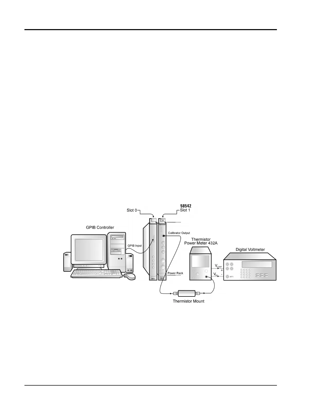
HP 432A Power Meter · DVM · Thermistor Power Meter · Thermistor Mount
Figure 4-1: Calibrator Reference Level Test Setup
 Loading...

