Calibration & Testing
Publication 21555, Rev. E, September 2002 4-11
4.4.2.1 Setup Parameters
The following setup parameters should be accomplished prior to performing the Power Linearity test:
4.4.2.2 Equipment Required
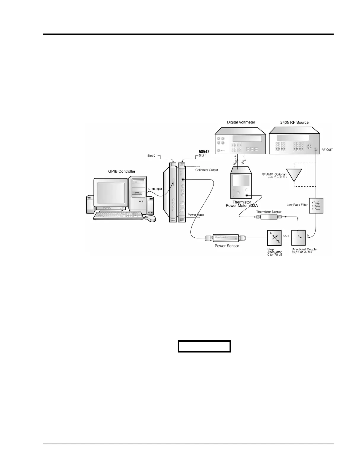
GPIB Controller · Digital Voltmeter · RF Signal Generator · Thermistor Power Meter · Directional Coupler · Step
Attenuator · Power Sensor
1. The power meter and sensor should be calibrated by following the instructions in Section4.3 of this
publication.
2. The Averaging is set to AUTO by entering:
SENS1:AVER:COUN:AUTO ON
(Enter SENS2 for channel 2)
Extreme care is required in the following procedure since the ac-
curacy requirements are critical to ensure the most accurate test
results.
Figure 4-3: Power Sensor Linearity Test Setup
CAUTION