58542 VXIbus Universal Power Meter
B-10 Publication 21555, Rev. E, September 2002
B.3 Power Sensor Calibration
This procedure is for calibrating a power sensor by remote control with a 58542 VXIbus Universal
Power Meter over the IEEE 488 interface bus. This procedure writes the cal factors to the sensor
EEPROM.
Power sensors have built-in EEPROM data that manage the cal factors by a set of frequencies entered
during calibration of the sensor at the factory. The user can program additional cal factors with special
data for user-specific frequencies. A cal factor expressed in dB is programmed for each factory-calibrated
frequency. The calibration process compares the measurement to the frequency standard and applies
the cal factor to offset frequency deviations.
B.3.1 Equipment Required
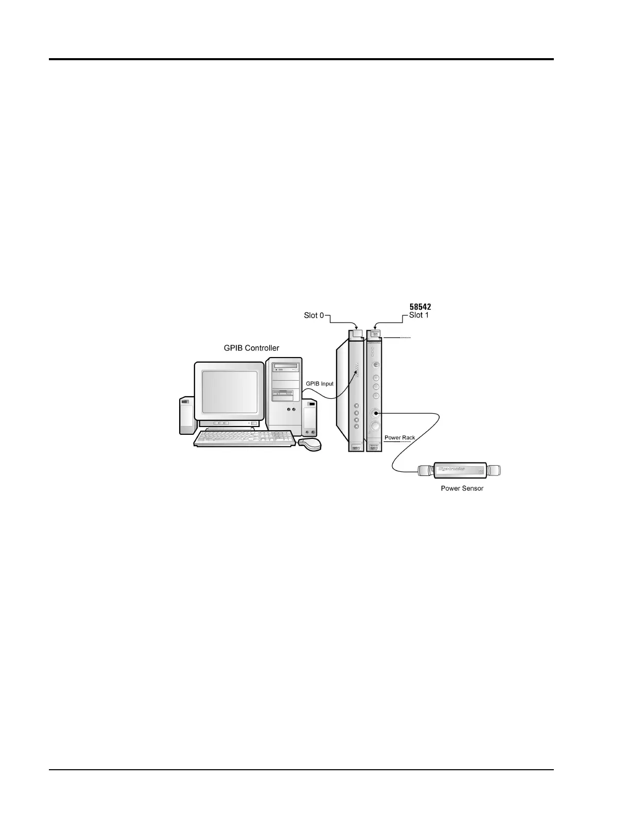
58542 VXIbus Universal Power Meter · GPIB Controller · Power Sensor
B.3.2 Procedure
Connect the power sensor to Channel 1 or 2 on the 58542 front panel and perform the following steps.
In this procedure, bold letters are commands; the query form of a command has a question mark (?) at
the end of the command. This form returns the data in the EEPROM.
1.
DIAG:SENS1 (or 2):EEPROM:READ
Read sensor 1 (or 2) EEPROM data into the 58542 editor buffer.
Example: OUTPUT@ PWR_MTR; DIAG:SENS1:EEPROM:READ
Figure B-1: Power Sensor Calibration Setup