Operation
Publication 21555, Rev. E, September 2002 2-55
2.5.33 Self-Test
■ *TST?
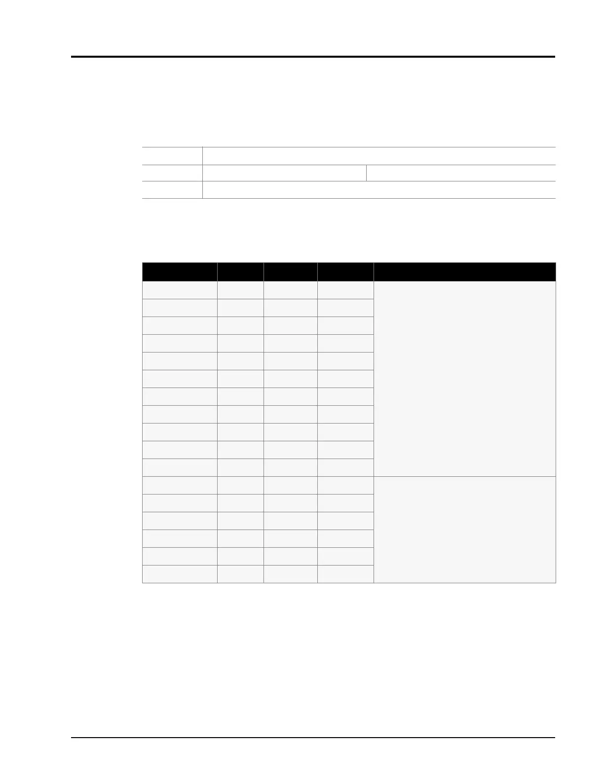
Table 2-5 lists the indications and limitations that will occur when the Self-Test command is applied to
the 58542 instrument. The Result, Minimum and Maximum indications are all given in millivolts.
*TST?
Syntax:
*TST?
Example: OUTPUT @PWR_MTR;*TST? ! QUERIES SELF-TEST RESULT
Response:
0 if all is OK, otherwise, it returns a value of 1.
Table 2-5: Self-Test Error Indication & Limitations
Error Number Result Minimum Maximum Test Description
100 0 0 50 OUTPUT DAC
This test steps the analog output DAC from
0volts to 10volts in 1 volt steps, and measures
the resultant output voltage with the system ADC.
It then compares the results with the limits shown
to the left and, if it is outside any limit, it will set the
error number corresponding to that voltage level.
101 1000 950 1050
102 2000 1900 2100
103 3000 2850 3150
104 4000 3800 4200
105 5000 4750 5250
106 6000 5700 6300
107 7000 6650 7350
108 8000 7600 8400
109 9000 8550 9450
110 10000 9500 10500
200 0 0 50 OFFSET DAC
This test steps the sensor input amplifier offset
DAC from 0volts to 5volts in 1volt steps, and
measures the resultant output voltage with the
system ADC. It then compares the results with the
limits stated to the left and, if outside any limit, it
will set the error number corresponding to that
voltage level.
201 1000 950 1050
202 2000 1900 2100
203 3000 2850 3150
204 4000 3800 4200
205 5000 4750 5250