58542 VXIbus Universal Power Meter
2-2 Publication 21555, Rev. E, September 2002
2.3 Initial Setup
The logical address and data transfer bus arbitration must be set up in the power meter before installing
the unit in a VXI mainframe and applying power. The following procedures define how to complete the
initial setup.
2.3.1 Logical Address
The VXI chassis Resource Manager identifies each unit in the system by its logical address. The VXI
logical address can range from 0 to 255. Addresses 0 and 255 are reserved for special functions:
Address 0 identifies the Resource Manager (slot and controller); address 255 permits the Resource
Manager to dynamically address the unit based on the chassis VXI slot.
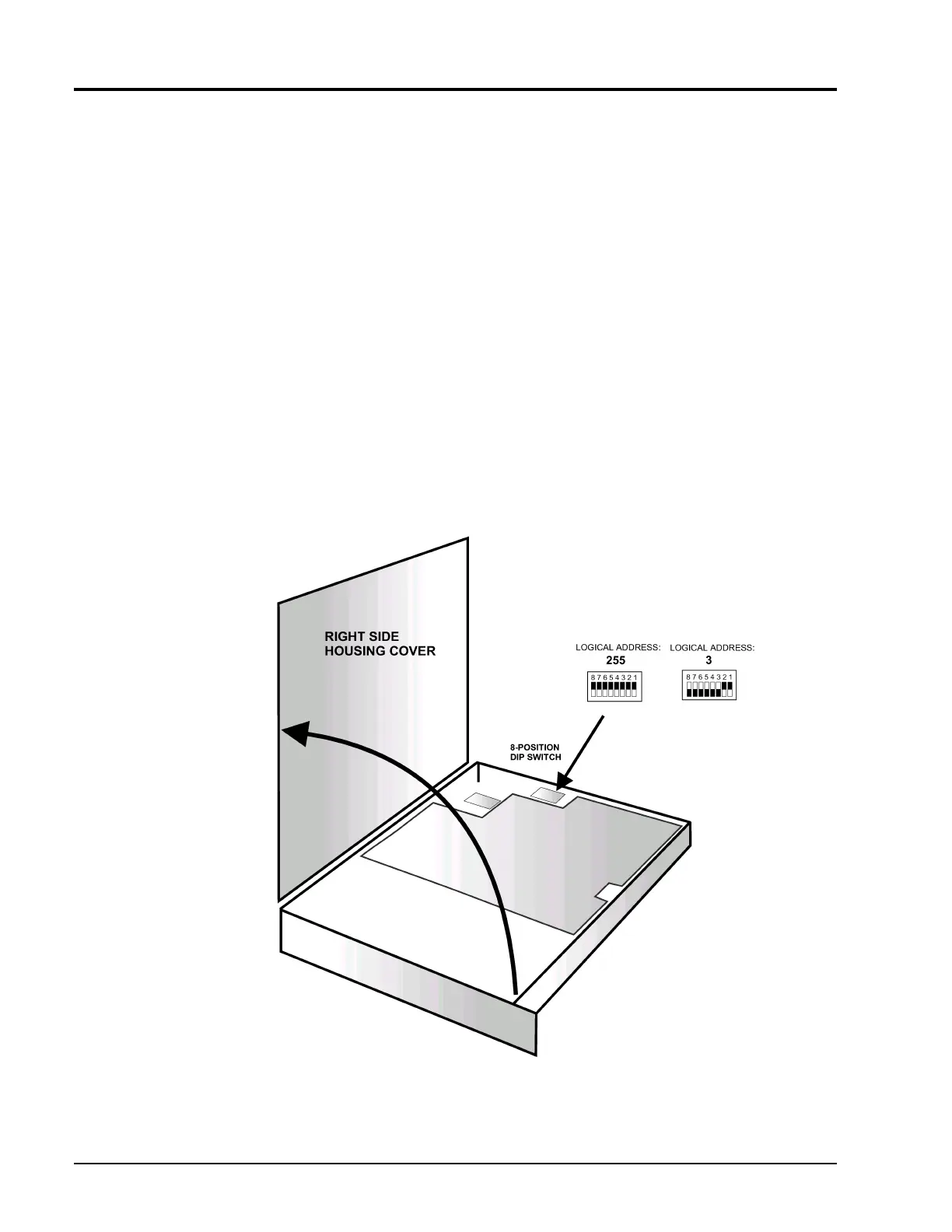
To change the logical address, set the respective sections on the eight position DIP switch. The switch is
accessible after removing the right cover (See Figure2-1).
The address is set with binary values of 0 to 255. Switch position 1 is the least significant bit of the
address. Figure2-1 illustrates logical address values of 3 (binary 00000011) and 255 (binary 11111111).
Giga-tronics ships the power meter with a logical address of 255 for dynamic configuration.
Figure 2-1: Setting the Logical Address