Publication 21555, Rev. E, September 2002 3-1
3
Theory of Operation
3.1 Introduction
This chapter contains a functional description of the electrical circuits contained on the PC board
assemblies of the 58542 VXI Universal Power Meter. Table 3-1 lists the circuit assemblies by their
reference designations and includes the assembly part number and schematic drawing number for each
board.
3.2 Circuit Description
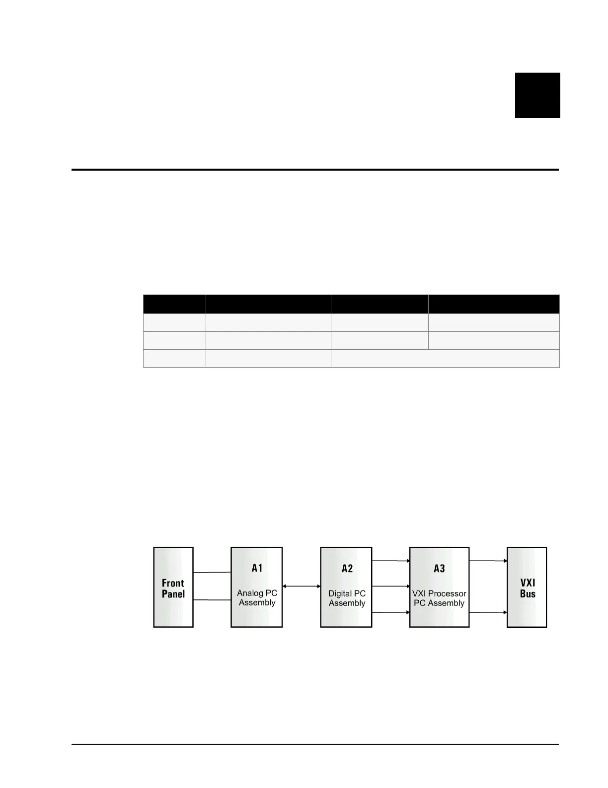
The 58542 Power Meter’s electrical circuitry resides mainly on three PC boards; the Analog PC Board
(A1), the Digital PC Board (A2) and the VXI Processor PC Board (A3). The Processor contains the
microprocessor, some ROM and RAM and the VXI interface chip. The remainder of the required ROM
and RAM is contained on the Digital board.
Two cables interface to the meter through the VXI Bus Interface connections on the rear panel. The Bus
Interface goes to the Processor board through connectors P1 and P2. Three front panel BNCs connect
to the Analog board. See DWG 21406 in Chapter 7 for specific interconnect information.
Table 3-1: VXI Power Meter Circuit Assemblies
Ref # Title Assembly P/N DWG
A1 Analog PC Assembly 21359 21360
A2 Digital PC Assembly 21356 21357
A3 VXI Processor PC Assembly This PCA is an OEM item
Figure 3-1: VXI Power Meter System Block Diagram