10
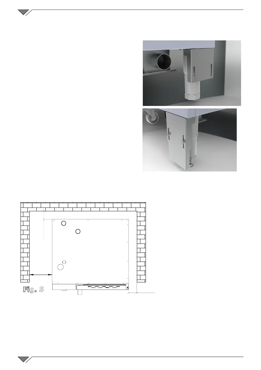
Ifitisdeemednecessary,theovenswithawheeledstructurecanbexed
totheoorusingthebracketssuppliedwiththeoven.
Remove the two screws that x the
rear foot to the frame, position the
blocking bracket as per Fig. 3 and use
the screws that have just been removed
toxittotheframe
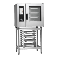
Placethe bracketontheoor asper
Fig. 4� Trace the position of the holes
ontheoorandblockthebracketusing
suitable xing systems. Perform the
same procedure on the rear foot on the
opposite side�
The oven should be installed exclusively
on a stable support�
Remove the packaging from the
appliance and make sure it is intact�
Arrange it in the place of use being
careful not to place it on top of or against
walls, bulkheads, partition walls, kitchen
furnitureorcoatingsinammablematerial.
Werecommendyoustrictlycomplywithre-preventionregulationsinforce.
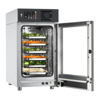
A minimum distance of
50 mm on each side must
be maintained between
the oven and the walls
or other equipment� It is
recommended to leave 500
mm space between the left
side of the oven and the
corresponding wall of the
room (Fig. 5) to allow the
oven to be installed easily
and facilitate successive
maintenance�
It is good practice to have the periodic maintenance of the ovens performed
every year by an authorised technician and in compliance with specic
regulations� On this occasion all controls regarding the operation of electric
components (switches, electronics, solenoid valves, heating elements, motors,
cooling fans, etc�) and the mechanical controls relative to functionality of the
doors, hinges, closing mechanisms, and gaskets will be performed�
Fig. 3
Fig. 4
50
mm
500
mm
50
mm
Fig. 5