• Cooling Air Out
OPTIC-4D has the following additional gas connections:
• Auxiliary Gas In
• Auxiliary Gas Out
4.2.1 Carrier Gas Line
OPTIC-4 needs a carrier gas supply which conforms to the following requirements:
Carrier Gas Type: Helium, Nitrogen or Hydrogen
Supply Pressure: 300- 700 kPa
Purity: 99.995%
The pressure and the column flow range vary accordingly to the supply pressure. To achieve
maximum specified pressure and flow settings a supply pressure of 700 kPa is necessary.
The gas supply can be provided by a cylinder with a pressure regulator or a laboratory gas supply
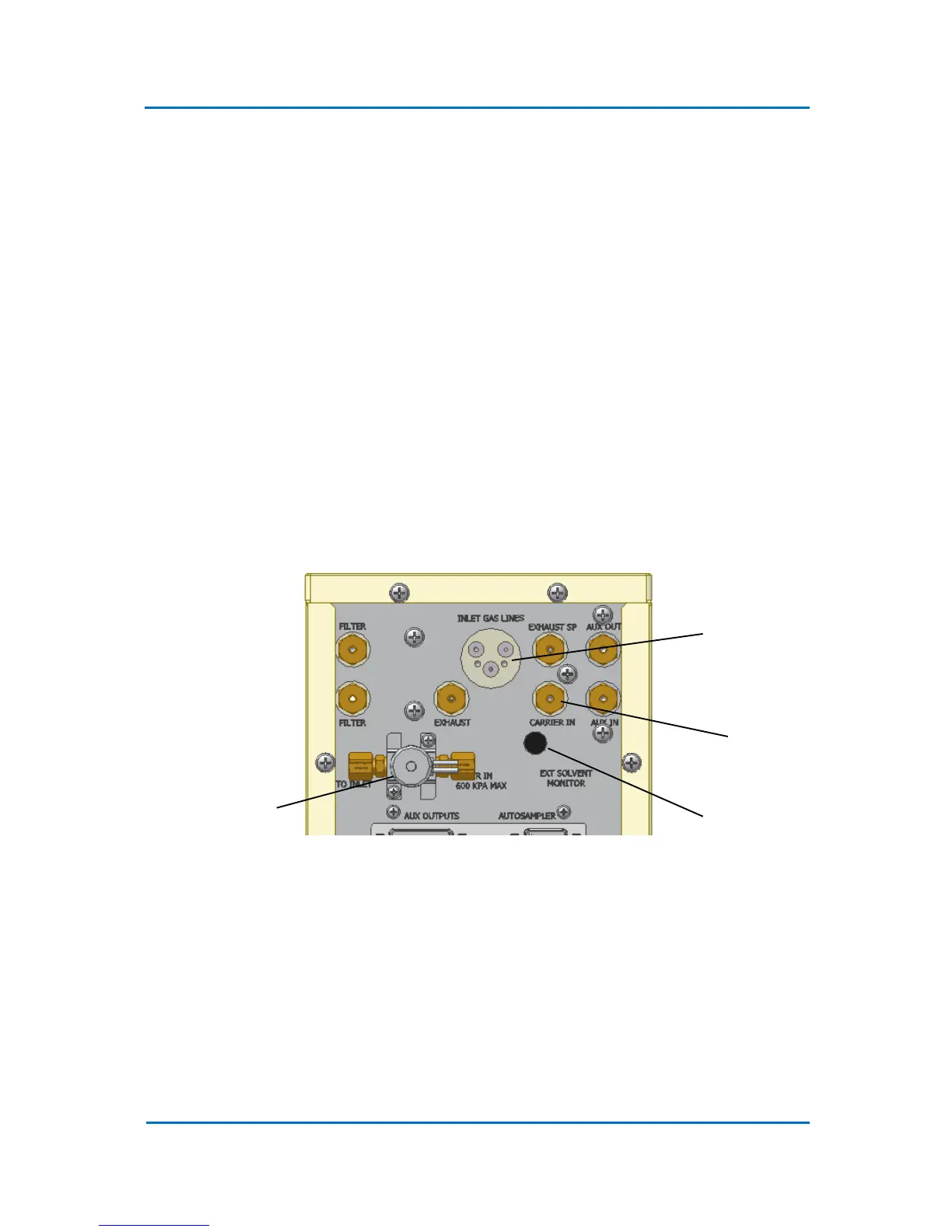
system. The carrier gas supply should be connected to the “Carrier In” port on the OPTIC-4 rear
panel (Fig. 4.1).
Figure 4.1 OPTIC-4 Rear Panel Gas Lines Connections
4.2.2 Inlet Gas Lines
The carrier, split, and septum purge lines of the OPTIC-4 inlet are attached to an EFC connection
plate. This plate ensures simple and leak free connections of the inlet gas lines to the OPTIC-4 EFC.
Remove blanking plate from the “Inlet Gas Lines” port (Fig. 4.1) on the back of the instrument and
screw the inlet EFC connection plate instead. Make sure that the sealing o-rings are in place. Check if
the gas line designations correspond to the connection designation on the EFC side (Fig. 4.2).