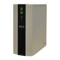
4. Hardware Installation
This section should be read carefully in conjunction with any specific instructions supplied with the
installation kit. Please follow these instructions with particular care if you are installing the OPTIC-4
on an instrument for which a dedicated installation kit is not available. Do not hesitate to contact the
supplier should you have any questions.
The installation of OPTIC-4 on a GC can be divided into the following steps:
• Installation of the inlet onto the chromatograph oven.
• Connection of the inlet to the EFC unit.
• Electrical connections.
• Installation of an appropriate liner and column.
• Installation of the cryogenic trap (OPTIC-4-SC and OPTIC-4-DC).
WARNING!
An GL Sciences representative must perform instrument installation and
configuration. To prevent potential injuries, contact an GL Sciences representative
if the instrument must be moved after installation.
WARNING!
It is important that both OPTIC-4 and the host GC are disconnected from the mains
supply until the installation is completed.
4.1 Installing the Inlet
To achieve the best results with OPTIC-4, the inlet should be installed directly into the oven
insulation, rather than into an inlet block. Fitting OPTIC-4 in this way ensures that it cools rapidly to
the required initial temperature.
4.1.1 Inlet Location
If OPTIC-4 is to be used for manual injection only, it can be fitted anywhere on the top of the oven
away from the standard GC inlet and detector blocks. The most convenient location is an existing
hole in the GC oven's inner skin. If OPTIC-4 is to be used with an autosampler, extra care is needed
in deciding upon the location. In many cases the removal or relocation of an existing inlet port will
be required. Ensure that the new inlet is aligned in all three axes such that its septum cap is co-
incident with that of the standard inlet.
OPTIC-4 Inlet body must be grounded to the GC’s chassis with the cable provided or to the oven base
plate, depending on the installation kit.