There are also connections for the gas chromatograph, autosampler, and auxiliary outputs. These
are configured in the Configuration Menu and I/O Menu accessed from the control software on the
PC (see the help file for the control software). The pin-outs of the connectors are described in
Appendix B “Rear Panel Connections”.
OPTIC-4-SC and OPTIC-4-DC have a “Cryotrap C. Valve” coupling for the cryotrap cooling valve
control. “Cryotrap TC” and “Cryotrap Heater” connections are used to connect the trap to the
control unit.
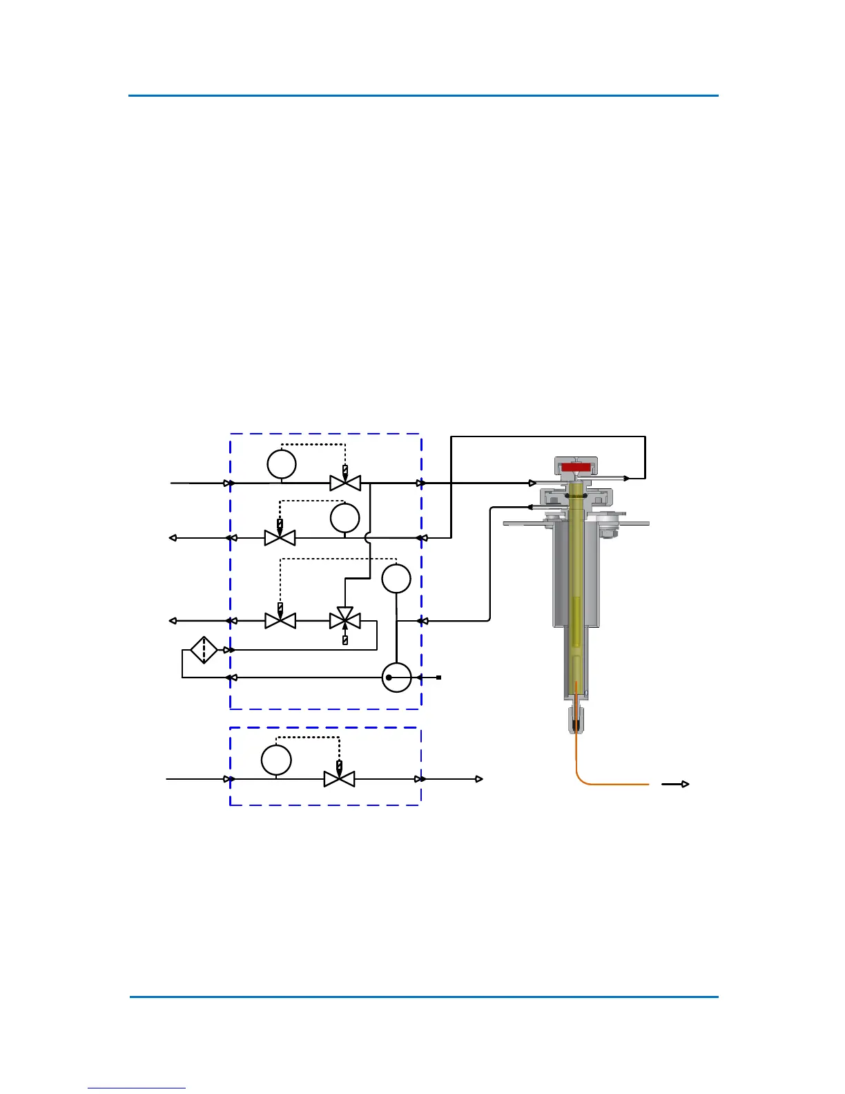
3.5 Flow Control System
Figure 3.4 shows a schematic diagram of the OPTIC-4 gas flow control system. Only OPTIC-4-D and
OPTIC-4-DC have the auxiliary gas flow control system.
Figure 3.4 OPTIC-4 Gas Control System
3.6 Inlet Hardware
The OPTIC-4 inlet assembly is installed on the host GC and is connected to the control unit by gas
lines and electrical cables. The installation of the inlet on the host GC is described in Chapter 4
“Hardware Installation”, and Figure 3.5 shows the details of the inlet.