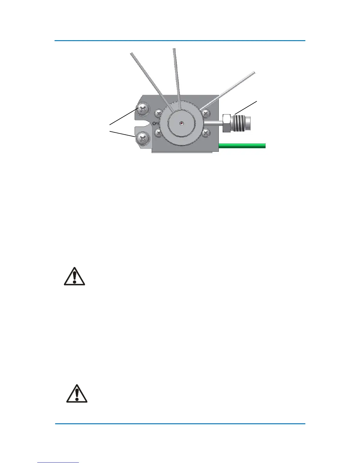
Figure 4.4 OPTIC-4 Inlet Top View
4.3 Electrical Connections
4.3.1 Inlet Power Connection
1. Connect the inlet power leads to the inlet power terminals (Fig. 4.3). Use only flat washers
supplied with the inlet. Screw the connections tightly. The power lead marked with a yellow
marker should be connected to the inlet base plate (upper electrode).
CAUTION!
It is important that good connections are made between the inlet power cable and
the inlet power terminals. A bad connection can result in a poor inlet operation
and the connection may become excessively hot.
2. The OPTIC-4PTV external solvent monitor is installed in the split line. Connect the solvent
monitor cable to the “Ext Solvent Monitor” connector on the rear panel.
3. Connect the inlet thermocouple to the “Inlet TC” connector on the rear panel of the
instrument.
4. Install the oven thermocouple supplied with the OPTIC-4 installation kit in the GC oven as
close as possible to the oven temperature sensor. Connect the thermocouple to the “GC TC”
connector on the OPTIC-4 rear panel.
CAUTION!
Do not confuse the GC oven thermocouple with the inlet thermocouple. This can
lead to a severe damage of the inlet.