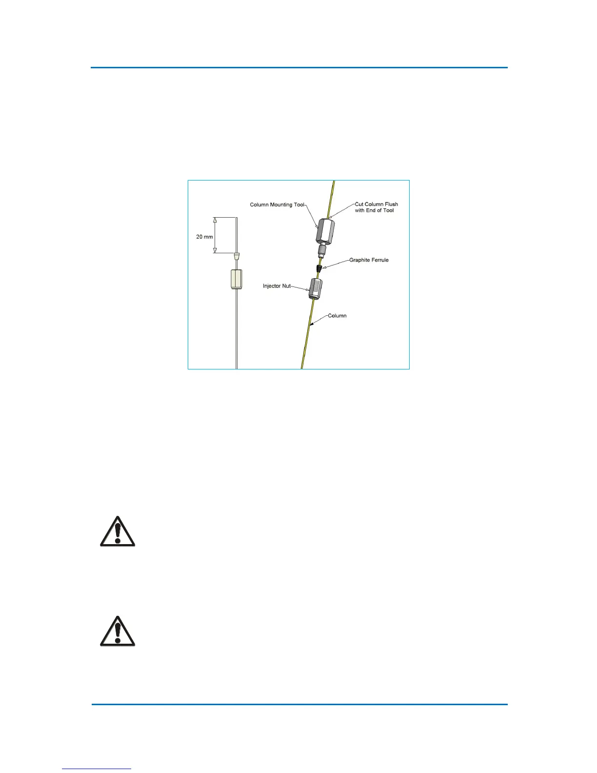
1. Install a column using proper ferrule and the column mounting tool. Push the column
through the inlet nut and ferrule (Fig. 4.5). The cone of the ferrule should go into the nut!
Avoid the use of the Vespel ferrules as these are likely to cause leaks.
2. Insert the end of the column into the column mounting tool so that it protrudes approx. 10
mm from the end. Tight the nut by hand, or use a key supplied with a standard kit, and cut
the protruding end of the column flash with the end of the tool.
Figure 4.5 Column Installation
3. Remove the capillary column from the tool. Insert the column into the inlet and secure it
by hand tightening the nut. Use the wrench supplied to turn it additionally half a turn.
4. On-column insert is fitted with the restriction towards the top of the inlet and the column
should be introduced into the inlet until the column tip engages in the bottom of the insert
restriction. Tighten the nut at the base of the inlet until the column is retained within the
inlet. Use the wrench supplied.
CAUTION!
Do not to tighten the base nut excessively. The inlet base is very fragile and can be
damaged easily. Never use Vespel ferrules.
5. When installation is completed, all connections should be leak tested with an electronic
gas leak detector (e. g. p/no 2702-19340 (LD239)).
CAUTION!
Under no circumstances should a soap solution or similar be used, as this would
contaminate the inlet and the column.