169
Detail program description - Wing mixers
Fl.pos
Diff.
Ail-tr
AI
Normal AILE
+100%
FL2
0 0%+100+100%+100+100%+100+100%
0%
0%
0%0%
0%
0%
0%
+100%
0%
0%
0%
FL
AILE2
FLAP
+100%
+100%
0%
0%
El
Fl
0 0%+100+100%+100+100%+100+100%
Delta/fl ying wing type models with more than two
wing fl aps
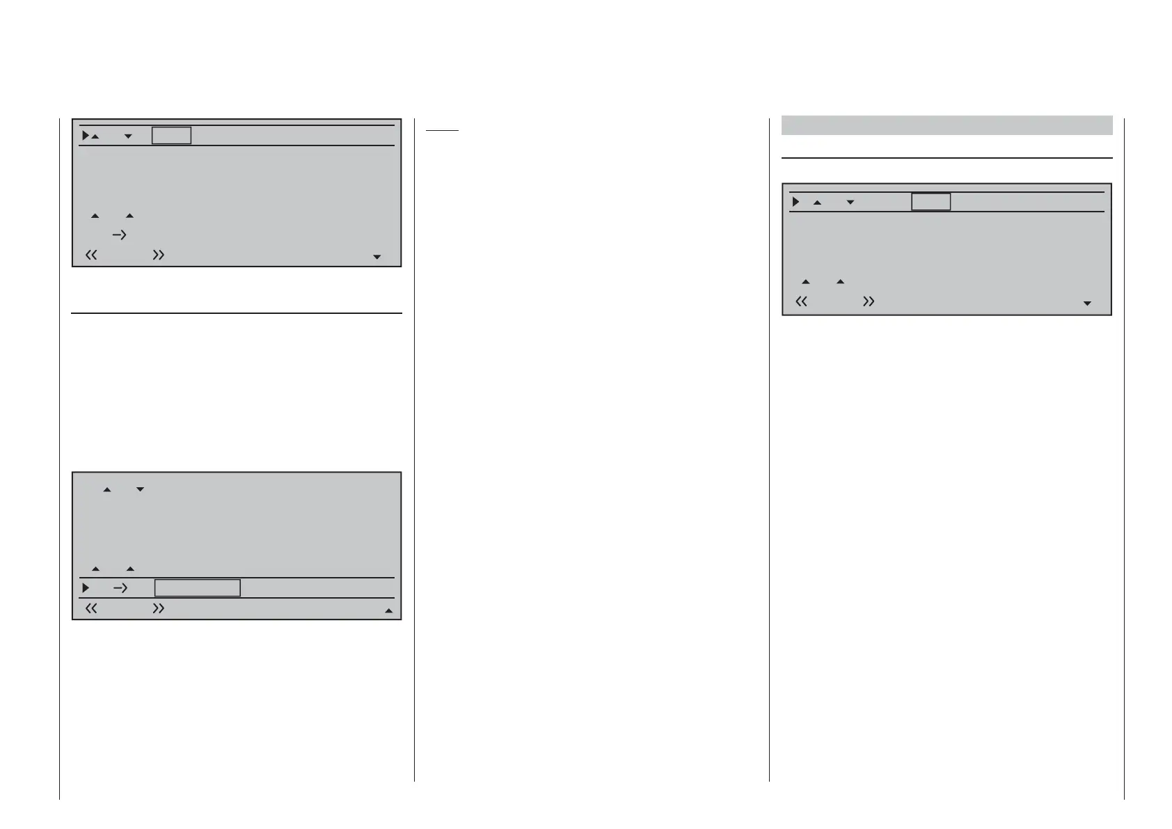
If the "ELEVON" tail type (for a delta-wing or fl ying
wing model) has been selected and number of wing
fl aps in the "Aileron/camber fl aps" line of the »Model
type« menu conforms to that menu's description, then
activation of the elevator joystick will normally result in
as little movement for both ailerons as for the inside
fl aps (FL) and, if present, (FL2). The reason for this is
the default mixer ratio of 0 % for all wing fl aps set for
the "EL¼FL" mixer found in the "Multi-fl ap" menu:
Fl.pos
Diff.
Ail-tr
Al
Normal AILE
+100%
FLAP
0%
0%
0%
+100%
0%
+100%
0%
+100%
0%
0%
0%0%
+100%
0%
0%
0%
FL
El
Fl
+100%
+100%
+100%
+100%
0%0%
0%
0%
0%0%
0%
0%
Accordingly, you must fi rst specify your desired
elevator control on the "EL ¼ FL" line. Take care to
ensure that up/down activation occurs in the right
sequence.
Note:
The "Brake settings" sub-menu (see next double
page) is also suitable for setting up the butterfl y
(crow) function with delta and fl ying wing models. In
fi ne-tuning the defl ection of the fl ap pairs AIL, FL and
(if present) FL2, however, ensure that the moments
created by one pair of fl aps compensate the moments
created by the other pair of fl aps in each case. For
example: the "up" effect of ailerons when defl ected up
should be compensated by a "down" effect from fl aps
when they are lowered.
Multi-fl ap menu
VAIW (Aileron ¼ camber fl aps)
(suppressed by "2AIL 1FL")
Fl.pos
Diff.
Ail-tr
Al
Normal AILE
+100%
FL2
FLAP
0%
0%
0%
+100%
0%
+100%
0%
+100%
0%
0%
0%0%
+100%
0%
0%
0%
FL
+100%
+100%
0%
0%
0%0%
The "VAIW" line can be used to make fl ight-phase
dependent settings for the percentage of aileron
action to result for the camber fl ap pair "FLAP" and, if
present, also "FL2" when aileron control is exercised.
(In the "AILE" column it is also possible to adjust the
defl ection of the aileron pair, if required.) Normally,
however, the fl aps should follow the ailerons with less
of a defl ection, i. e. the mixer ratio should be smaller
than 100 %.
The adjustment range of -150 % to +150 % means
the direction of defl ection can be adjusted, depending
on the direction of rotation of the servos, to suit the
ailerons.
A simultaneous tap on the cd or ef keys of the
right touch pad (CLEAR) will reset the given active
(inverse video) fi eld to its default value shown in the
fi gure.

 Loading...


